
Page 56 - Read Online
P. 56
Page 4 of 21 Guo et al. Energy Mater. 2025, 5, 500041 https://dx.doi.org/10.20517/energymater.2024.214
Figure 1. Schematic diagram of the surface modification strategies in solid lithium polymer battery.
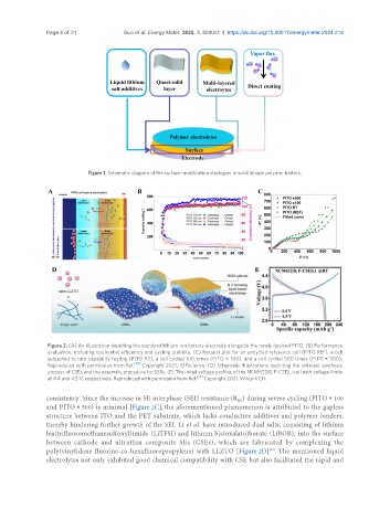
Figure 2. (A) An illustration depicting the standard lithium-ion battery electrode alongside the newly devised PITO. (B) Performance
evaluation, including coulombic efficiency and cycling stability. (C) Nyquist plot for an uncycled reference cell (PITO REF), a cell
subjected to rate capability testing (PITO RT), a cell cycled 100 times (PITO × 100), and a cell cycled 500 times (PITO × 500).
[38]
Reproduced with permission from Ref. Copyright 2021, IOPscience. (D) Schematic illustrations depicting the intricate synthesis
process of CSEs and the assembly procedure for SSBs. (E) The initial voltage profiles of the NCM622|B, F-CSE|Li cell with voltage limits
at 4.4 and 4.5 V, respectively. Reproduced with permission from Ref. [39] Copyright 2021, Wiley-VCH.
consistency. Since the increase in SE interphase (SEI) resistance (R ) during severe cycling (PITO × 100
SEI
and PITO × 500) is minimal [Figure 2C], the aforementioned phenomenon is attributed to the gapless
structure between ITO and the PET substrate, which lacks conductive additives and polymer binders,
thereby hindering further growth of the SEI. Li et al. have introduced dual salts, consisting of lithium
bis(trifluoromethanesulfonyl)imide (LiTFSI) and lithium bis(oxalato)borate (LiBOB), into the surface
between cathode and ultrathin composite SEs (CSEs), which are fabricated by complexing the
[39]
poly(vinylidene fluorine-co-hexafluoropropylene) with LLZTO [Figure 2D] . The mentioned liquid
electrolytes not only exhibited good chemical compatibility with CSE but also facilitated the rapid and