
Page 201 - Read Online
P. 201
Guo et al. Microstructures 2023;3:2023038 https://dx.doi.org/10.20517/microstructures.2023.30 Page 13 of 30
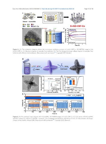
Figure 5. (A) The schematic diagram shows the microwave synthesis process of S-rGO-CNT-Co. (B) HRTEM image of the
S-rGO-CNT-Co. (C) Structure diagram of seawater flow batteries. (D) The first charge-discharge voltage diagram of seawater flow
batteries with different electrocatalysts. (Reproduced with permission [97] . Copyright 2017, Elsevier).
Figure 6. (A) The synthesis route diagram of D-FeCo@NHC. (B) HRTEM images of S-rGO-CNT-Co. (C) LSV curves of D-FeCo@NHC
and Pt/C catalyst for ORR in 0.1 M KOH + seawater. (D) Computed work functions of D-FeCo//D-NC. (E) Galvanostatic discharge-
charge cycling stability of liquid ZAB. (Reproduced with permission [98] . Copyright 2023, Elsevier).