
Page 123 - Read Online
P. 123
Page 12 of 20 Li et al. Microstructures 2023;3:2023024 https://dx.doi.org/10.20517/microstructures.2023.09
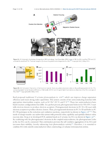
Figure 11. (A) Schematic illustration of magnetron CBD technology. High-Resolution SEM images of (B) Au NCs modified FTO and (C)
colloidal Au modified FTO. The inset image in (B) shows the global view of deposited Au NCs [85] . Copyright 2021, Wiley-VCH.
Figure 12. (A) Schematic illustration of hot electron transfer from an excited plasmonic state on the gold nanoparticle to the TiO
2
conduction band. Formal Quantum Efficiency (FQE) under (B) UV and (C) green light illumination as a function of Au NCs coverage on
[86]
TiO P25 . Copyright 2018, Wiley-VCH.
2
Bard proposed traditional Z-scheme photocatalysts in 1979 , which can improve charge separation
[91]
efficiency and retain strong redox capabilities. This system consists of two semiconducting materials with
appropriate intermediate couples, such as Fe /Fe , IO /I , and I /I . These two semiconductors have
2+
3+
3-
-[92]
-
3-
band structure configurations that differ. In a perfect process, photogenerated holes in the VB of PC I react
with electron donors to produce electron acceptors. Photogenerated electrons in PC II’s CB react with
electron acceptors to produce electron donors. Then, photogenerated electrons in PC I’s CB and holes in PC
II’s VB participate in the reduction and oxidation reactions, respectively (as shown in Figure 13) [93,94] . This
mode of charge transfer can endow this system with powerful redox capability and spatially distinct redox
[95]
reaction sites. Deng et al. developed PCR catalysts based on Z-scheme Au NCs (as shown in Figure 14) .
By combining with the photogenerated electrons in the coupled semiconductor, the photogenerated holes
in the Au NCs can be consumed. This combination prevents the self-oxidative aggregation of Au NCs and
increases their stability, thereby enhancing their photocatalytic activity . Therefore, it is essential to
[95]
combine NCs with suitable semiconductors when constructing a Z-scheme heterojunction system.