
Page 24 - Read Online
P. 24
Schiavone et al. Modelling of metallic and polymeric stents
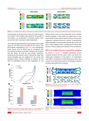
Figure 7: Von Mises stress (MPa) contour plot for the Elixir (left) and Xience (right) stents in (A) fully crimped state and (B) spring-back state
local damage to plaque/artery where the high stresses Mises) stress, and it is a key parameter used in ductile
are located. This condition also leads to the growth of fracture analysis. In this study, we mainly focus on the
new tissue, e.g. proliferation of smooth muscle cells, stress state of stent-artery system during crimping and
around the stent, causing in-stent restenosis. expansion, instead of fracture or failure. Consequently,
stress triaxiality is not presented. But we aim to look into
The maximum principal stress on the plaque had a peak
value of 1.43 MPa and 0.54 MPa for the Xience and this in future studies when considering the failure and
Elixir stents, respectively [Figure 10]. The considerably fracture of stent, plaque and arteries in the simulations.
lower stress level for Elixir stent is consistent with Effect of residual stresses caused by crimping
the reduced property mismatch between the polymer
and the artery as well as less arterial expansion As shown in Figure 7, crimping introduced severe
achieved by the polymer stent. It should be noted that residual stresses into the stent, which can affect the
stress triaxiality was not explored for the stents and subsequent expansion of the device. To understand
diseased artery. Stress triaxiality is defined as the such effect, simulations of stent deployment were also
ratio of hydrostatic stress to the equivalent (or von carried out for both stents without including the residual
stresses generated from crimping.
Figure 9: Contour plot of the von Mises stress (MPa) on (A) Elixir
and (B) Xience stents after deployment
Figure 10: Contour plot of maximum principal stress (MPa) on the
Figure 8: (A) Diameter change against pressure; (B) recoiling and stenotic plaque after stent deployment: (A) Elixir and (B) Xience
dogboning effects during deployment of Elixir and Xience stents stents
Vessel Plus ¦ Volume 1 ¦ March 31, 2017 17