
Page 70 - Read Online
P. 70
Rao. Vessel Plus 2022;6:24 https://dx.doi.org/10.20517/2574-1209.2021.91 Page 3 of 23
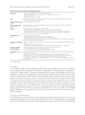
Table 1. Summary of ultrasound, echo, and Doppler techniques
Ultrasound - Sound above the audible range, usually > 20,000 cycles/s
- Ultrasound used for medical purposes is within 2 to 10 MHz (millions of cycles/s)
- Obeys laws of reflection
- Produced by “Piezoelectric” crystals
Echo Reflected ultrasound. When ultrasound strikes an interface between two materials that have different acoustic
impedances, it is reflected, producing an echo
Motion or “M” mode echo Echo recording against time on X-axis
[Figure 1]
Two-dimensional (2D) Echo recording with spatial information added with respect to the location of the beam at the time the info is
received (line locater circuitry)
echo [Figure 2]
Doppler - The low magnitude echoes from blood cells are studied
- Apparent shift of transmitted frequency occurs as a result of the motion of the target
- Frequency shift of transmitted to received wave fronts are analyzed by multiple methods (see the text)
- Velocity is calculated: V = C × F/2 (TF) × Cosine of intercept angle, where V is velocity; C, speed of the
ultrasound; F, frequency shift; TF, transmitted frequency
Pulsed Doppler [Figures 3 - Uses single crystal, similar to echo
and 4] - Small area along ultrasonic beam can be studied - “range gating”
- Advantage: exact location of sample volume can be chosen by the examiner
- Disadvantage: high-velocity flows cannot be recorded because of the low Nyquist limit of the pulsed Doppler and
aliasing of the Doppler signal at high velocities
Continuous wave Doppler - Uses two crystals; one crystal continuously sends ultrasound and the other crystal receives reflected ultrasound
[Figure 5] (echo)
- Advantage: can record high flow velocity
- Disadvantage: records Doppler data along the line of the ultrasound beam and cannot be range gated
High pulse repetition - Similar to pulsed Doppler in that it uses a single crystal and uses pulsed ultrasound
frequency Doppler - Uses several pulses which are in the body simultaneously
- Three or more sample volumes are placed along the ultrasound beam
Color Doppler [Figures 6 - Multi-gated pulsed Doppler technique which superimposes color-coded Doppler flow information on a real-time
and 7] 2D image; it is a 2D Doppler
- Multiple sample volumes are placed along the ultrasonic beam and on many such ultrasonic beams
- The velocities are color-coded so that the velocity of blood moving towards the transducer is red and blood
moving away from the transducer is blue. Such assignment is conventional, but can be changed
- Turbulent flow is expressed as a mosaic pattern [Figure 7] which is a mixture of yellow and green superimposed
on red and blue
Reproduced from Ref. [19] .
PW Doppler
In PW Doppler, a solitary crystal, comparable to the standard echocardiogram is used. A tiny site along the
ultrasonography beam is examined; this is named “range gating”. The site from where range gating is
secured is the “sample volume”. The position and magnitude of the sample volume [Figures 3 and 4] may be
changed by the examiner. This technique is commonly utilized to show normal blood flow velocity values
and to locate abnormalities of flow disorder. The benefit of this method is that the precise site of the sample
volume is selected by the operator, and the location of the flow abnormality can be pinpointed. However,
the drawback of the pulse Doppler technique is that flow velocities of high magnitude are not recorded
secondary to small Nyquist perimeter of the PW Doppler and aliasing of the Doppler at a higher velocity.
Multiple techniques such as changing baseline to bottom or top, totaling the wraparound amount
[Figure 5], utilizing lesser frequency transducer, decreasing the distance to the target, improving the
intercept angle have been used in the past to avoid aliasing. However, at the present time, CW and HPRF
Doppler techniques are being utilized to quantify velocities greater than those documented by the PW
Doppler technique.
CW Doppler and HPRF Doppler
In CW Doppler, 2 crystals are utilized, 1 crystal constantly transmits the ultrasound, and the second crystal
collects the Doppler signal. The benefits of this system are that it is able to capture high flow velocity signals.
However, the drawback is that this system looks at Doppler information along the beam of the ultrasound