
Page 97 - Read Online
P. 97
Page 12 of 16 Sun et al. Soft Sci. 2025, 5, 35 https://dx.doi.org/10.20517/ss.2025.21
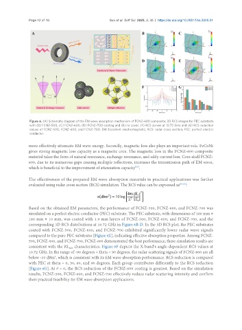
Figure 6. (A) Schematic diagram of the EM wave absorption mechanism of FCNZ-600 composite; 3D RCS images for PEC substrate
with (B) FCNZ-500, (C) FCNZ-600, (D) FCNZ-700 coating and (E) no cover; (F) RCS curves at 10.72 GHz and (G) RCS reduction
values of FCNZ-500, FCNZ-600, and FCNZ-700. EM: Excellent electromagnetic; RCS: radar cross section; PEC: perfect electric
conductor.
more effectively attenuate EM wave energy. Secondly, magnetic loss also plays an important role. FeCoNi
gives strong magnetic loss capacity as a magnetic core. The magnetic loss in the FCNZ-600 composite
material takes the form of natural resonance, exchange resonance, and eddy current loss. Core-shell FCNZ-
600, due to its numerous gaps causing multiple reflections, increases the transmission path of EM wave,
which is beneficial to the improvement of attenuation capacity .
[61]
The effectiveness of the prepared EM wave absorption materials in practical applications was further
evaluated using radar cross section (RCS) simulation. The RCS value can be expressed as [62,63] :
Based on the obtained EM parameters, the performance of FCNZ-500, FCNZ-600, and FCNZ-700 was
simulated on a perfect electric conductor (PEC) substrate. The PEC substrate, with dimensions of 180 mm ×
180 mm × 10 mm, was coated with 1.9 mm layers of FCNZ-500, FCNZ-600, and FCNZ-700, and the
corresponding 3D RCS distributions at 10.72 GHz in Figure 6B-D. In the 3D RCS plot, the PEC substrates
coated with FCNZ-500, FCNZ-600, and FCNZ-700 exhibited significantly lower radar wave signals
compared to the pure PEC substrates [Figure 6E], indicating effective absorption properties. Among FCNZ-
500, FCNZ-600, and FCNZ-700, FCNZ-600 demonstrated the best performance, these simulation results are
consistent with the RL characteristics. Figure 6F depicts the X-band’s angle-dependent RCS values at
min
10.72 GHz. In the range of -90 degrees < theta < 90 degrees, the radar scattering signals of FCNZ-600 are all
2
below -10 dBm , which is consistent with its EM wave absorption performance. RCS reduction is compared
with PEC at theta = 0, 30, 60, and 90 degrees. Each group contributes differently to the RCS reduction
[Figure 6G]. At θ = 0, the RCS reduction of the FCNZ-600 coating is greatest. Based on the simulation
results, FCNZ-500, FCNZ-600, and FCNZ-700 effectively reduce radar scattering intensity and confirm
their practical feasibility for EM wave absorption applications.