
Page 93 - Read Online
P. 93
Page 8 of 16 Sun et al. Soft Sci. 2025, 5, 35 https://dx.doi.org/10.20517/ss.2025.21
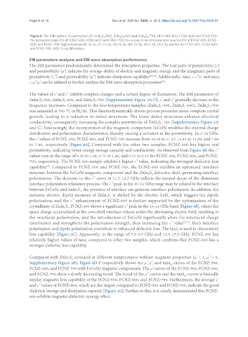
Figure 3. The XRD pattern of synthesized (A) ZnIn S -500, ZnIn S -600 and ZnIn S -700; (B) FCNZ-500, FCNZ-600 and FCNZ-700;
2 4
2 4
2 4
the hysteresis loops (C) of FCNZ-500, FCNZ-600 and FCNZ-700; the survey X-ray photoelectron spectra (D) of FCNZ-500, FCNZ-
600, and FCNZ-700; high revolution (E) Fe 2p, (F) Co 2p, (G) Ni 2p, (H) Zn 2p, (I) In 3d, (J) S 2p spectra for FCNZ-500, FCNZ-600
and FCNZ-700. XRD: X-ray diffraction.
EM parameters analysis and EM wave absorption performance
The EM parameters predominantly determined the absorption properties. The real parts of permittivity (ε′)
and permeability (μ') indicate the storage ability of electric and magnetic energy and the imaginary parts of
permittivity (ε'') and permeability (μ'') indicate dissipation capability [43,44] . Additionally, tanδ = ε''/ε' and tanδμ
ε
[45]
= μ''/μ' can be utilized to further analyze the EM wave absorption properties .
The values of ε' and ε'' exhibit complex changes and a certain degree of fluctuation. The EM parameters of
ZnIn S -500, ZnIn S -600, and ZnIn S -700 [Supplementary Figure 3A-C], ε' and ε" gradually decrease as the
2 4
2 4
2 4
frequency increases. Compared to the low-temperature samples (ZnIn S -500, ZnIn S -600), ZnIn S -700
2 4
2 4
2 4
was annealed at 700 °C in H /Ar. This thermodynamically driven process promotes more complete crystal
2
growth, leading to a reduction in defect structures. The lower defect structures enhance electrical
conductivity, consequently increasing the complex permittivity of ZnIn S -700 [Supplementary Figure 3A
2 4
and C]. Interestingly, the incorporation of the magnetic component FeCoNi modifies the internal charge
distribution and polarization characteristics, thereby causing a variation in the permittivity. In 2-18 GHz,
the ε' values of FCNZ-500, FCNZ-600, and FCNZ-700 decrease from 10.56 to 11.27, 11.41 to 11.99, and 7.88
to 7.80, respectively [Figure 4A]. Compared with the other two samples, FCNZ-600 has higher real
permittivity, indicating better energy storage capacity and conductivity. As observed from Figure 4B, the ε''
values vary in the range of 0.30 to 1.96, 0.71 to 1.86, and 0.51 to 0.55 for FCNZ-500, FCNZ-600, and FCNZ-
700, respectively. The FCNZ-600 sample exhibits a higher ε'' value, indicating the strongest dielectric loss
capability . Compared to FCNZ-500 and FCNZ-700, the FCNZ-600 exhibits an optimized interface
[46]
structure between the FeCoNi magnetic component and the ZnIn S dielectric shell, promoting interface
2 4
polarization. The decrease in the ε'' curve at 11.5-12.5 GHz reflects the natural decay of the dominant
interface polarization relaxation process. The ε'' peak in the 10-14 GHz range may be related to the interface
between FeCoNi and ZnIn S , the presence of interface can generate interface polarization. In addition, the
2 4
intrinsic electric dipole moment of ZnIn S is shifted by the electric field, which triggers the dipole
2 4
polarization, and the ε'' enhancement of FCNZ-600 is further supported by the optimization of the
crystallinity of ZnIn S . FCNZ-600 shows a significant ε'' peak in the 10-14 GHz band [Figure 4B], where the
2 4
space charge accumulated at the core-shell interface relaxes under the alternating electric field, resulting in
the interfacial polarization, and the introduction of FeCoNi significantly alters the interfacial charge
distribution and strengthens the polarization strength, thus increasing the ε'' value [47-51] . Both interface
polarization and dipole polarization contribute to enhanced dielectric loss. The tanδ is used to characterize
ε
loss capability [Figure 4C]. Apparently, in the range of 7.5-9.5 GHz and 13.5-17.5 GHz, FCNZ-600 has
relatively higher values of tanδ compared to other two samples, which confirms that FCNZ-600 has a
ε
stronger dielectric loss capability.
Compared with ZnIn S annealed at different temperatures without magnetic properties (μ' ≈ 1, μ'' ≈ 0,
2 4
Supplementary Figure 3B), Figure 4D-F respectively shows the μ', μ'', and tanδ curves of the FCNZ-500,
μ
FCNZ-600, and FCNZ-700 with FeCoNi magnetic components. The μ' curves of the FCNZ-500, FCNZ-600,
and FCNZ-700 show a slowly decreasing trend. The trend of the μ'' curves and the tanδ curves is basically
μ
similar magnetic loss capability of the FCNZ-500, FCNZ-600, and FCNZ-700. Furthermore, the average ε'
and ε'' values of FCNZ-600, which are the largest compared to FCNZ-500 and FCNZ-700, indicate the good
dielectric storage and dissipation capacity [Figure 4G]. Further to this, it is clearly demonstrated that FCNZ-
600 exhibits magnetic-dielectric synergy effect.