
Page 43 - Read Online
P. 43
Wang et al. Soft Sci 2024;4:41 https://dx.doi.org/10.20517/ss.2024.53 Page 25 of 43
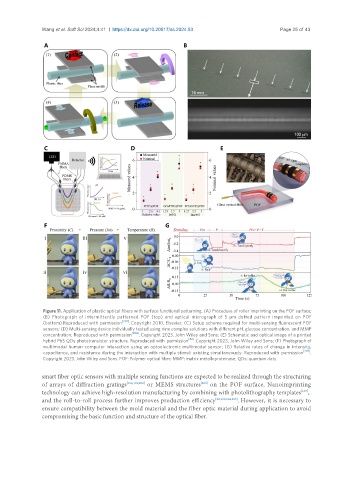
Figure 11. Application of plastic optical fibers with surface functional patterning. (A) Procedure of roller imprinting on the POF surface;
(B) Photograph of intermittently patterned POF (top) and optical micrograph of 5 μm dotted pattern imprinted on POF
(bottom).Reproduced with permission [202] . Copyright 2010, Elsevier; (C) Setup scheme required for multi-sensing fluorescent POF
sensors; (D) Multi-sensing device individually tested using nine complex solutions with different pH, glucose concentration, and MMP
concentration. Reproduced with permission [206] . Copyright 2023, John Wiley and Sons; (E) Schematic and optical image of a printed
hybrid PbS QDs phototransistor structure. Reproduced with permission [42] . Copyright 2023, John Wiley and Sons; (F) Photograph of
multimodal human-computer interaction using an optoelectronic multimodal sensor; (G) Relative rates of change in intensity,
capacitance, and resistance during the interaction with multiple stimuli existing simultaneously. Reproduced with permission [201] .
Copyright 2023, John Wiley and Sons. POF: Polymer optical fiber; MMP: matrix metalloproteinase; QDs: quantum dots.
smart fiber optic sensors with multiple sensing functions are expected to be realized through the structuring
[200]
of arrays of diffraction gratings [106,199,203] or MEMS structures on the POF surface. Nanoimprinting
[107]
technology can achieve high-resolution manufacturing by combining with photolithography templates ,
and the roll-to-roll process further improves production efficiency [22,199,204,205] . However, it is necessary to
ensure compatibility between the mold material and the fiber optic material during application to avoid
compromising the basic function and structure of the optical fiber.