
Page 127 - Read Online
P. 127
Page 20 of 32 Keum et al. Soft Sci 2024;4:34 https://dx.doi.org/10.20517/ss.2024.26
Table 3. Comparison of light-emitting types, colors, stretchability, maximum brightness, and turn-on voltage of stretchable light-
emitting devices
Light-emitting EML materials (color) Stretchability Max. Brightness Turn-on voltage Ref.
2
type (%) (cd/m ) (V)
PLED PDY-132 (yellow) 100% 7,450 - [99]
OLED PTrz-tBuCz/TPA-AQ (red) 125% 2,175 4.75 [101]
PDKCD (green)
PTrz-tBuCz (blue)
PLED Spiro-red/SEBS (red) 100% 1,000 5 [97]
Spiro-green/SEBS (green)
PFO/SEBS (blue)
OLED PVK/Hex-Ir(phq) (red) 100% 5,400 - [100]
3
PVK/Ir(ppy) (green)
3
PVK/Flrpic (blue)
QLED CdSe/ZnS QDs (red, green, and 50% 15,170 3.2 [119]
blue)
Pe-QD LED MAPbBr QDs (green) 50% 3,187 3.2 [126]
3
EML: Emitting layer; SS: subthreshold swing; PLED: polymer-type light-emitting diode; PDY-132: Super Yellow (SY); OLED: organic light-emitting
diode; PTrz-tBuCz/TPA-AQ, PDKCD, PTrz-tBuCz: thermally activated delayed fluorescence (TADF) polymers; SEBS: styrene-ethylene-butylene-
styrene; PFO: poly(9,9-di-n-octylfluorenyl-2,7-diyl); PVK: poly(9-vinyl carbazole); Flrpic: bis[2-(4,6-difluorophenyl)pyridinato-C2,N]-
(picolinato)iridium(III); Hex-Ir(phq) : tris[2-(4-n-hexylphenyl)-quinoline]iridium(III); Ir(ppy) : tris(2-phenylpyridine)iridium(III); QD: quantum
3
3
dot.
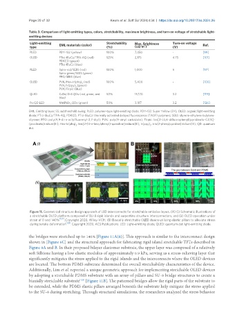
Figure 11. Geometrical structure design approach of LED interconnects for stretchable emissive layers. (A) (i) Schematic illustrations of
a stretchable OLED platform composed of SU-8 rigid islands and serpentine structure interconnectors, and (ii) OLED operation under
[127]
strain of 0 and 140% . Copyright 2020, Wiley-VCH; (B) Biaxially stretchable OLED device utilizing elastic pillars to alleviate stress
[128]
during tensile deformation . Copyright 2020, ACS Publications. LED: Light-emitting diode; QLED: quantum dot light-emitting diode.
the bridges were stretched up to 140% [Figure 11A(ii)]. This approach is similar to the interconnect design
shown in [Figure 6C] and the structural approach for fabricating rigid island stretchable TFTs described in
Figure 8A and B. In their proposed bilayer elastomer substrate, the upper layer was composed of a relatively
soft Silbione having a low elastic modulus of approximately 0.9 kPa, serving as a stress-relieving layer that
significantly mitigates the stress applied to the rigid islands and the interconnects where the OLED devices
are located. The bottom PDMS substrate determined the overall stretchability characteristics of the device.
Additionally, Lim et al. reported a unique geometric approach for implementing stretchable OLED devices
by adopting a stretchable PDMS substrate with an array of pillars and SU-8 bridge structures to create a
[128]
biaxially stretchable substrate [Figure 11B]. The patterned bridges allow the rigid parts of the substrate to
be extended, while the PDMS elastic pillars arranged beneath the substrate help mitigate the stress applied
to the SU-8 during stretching. Through structural simulations, the researchers analyzed the stress behavior