
Page 70 - Read Online
P. 70
Shin et al. Soft Sci 2024;4:22 https://dx.doi.org/10.20517/ss.2024.03 Page 9 of 13
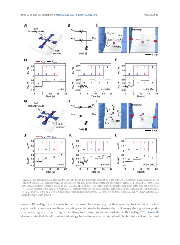
Figure 4. Fully soft logic gates based on the Schottky diode. (A) Schematic illustration of the fully soft OR gate; (B) Circuit diagram of the
fully soft OR gate; (C) Optical images of the fully soft OR gate before strain (left) and after strain (right); (D-F) V and V of the fully
out
in
soft OR gate under mechanical strains of 0% (D), 30% (E), and 0% (released) (F); (G) Schematic illustration of the fully soft AND gate;
(H) Circuit diagram of the fully soft AND gate; (I) Optical images of the fully soft AND gate before strain (left) and after strain (right);
(J-L) V and V of the fully soft OR gate under mechanical strains of 0% (J), 30% (K), and 0% (released) (L). V : Input voltage; V :
out
out
in
in
output voltage; GND: ground.
smooth DC voltage, which can be further improved by integrating it with a capacitor. In a rectifier circuit, a
capacitor functions to smooth out pulsating electric signals by storing electrical energy during voltage peaks
and releasing it during troughs, resulting in a more consistent and stable DC voltage [41-43] . Figure 5E
demonstrates that the skin-interfaced energy harvesting system, equipped with both a fully soft rectifier and