
Page 71 - Read Online
P. 71
Nagwade et al. Soft Sci 2023;3:24 https://dx.doi.org/10.20517/ss.2023.12 Page 5 of 25
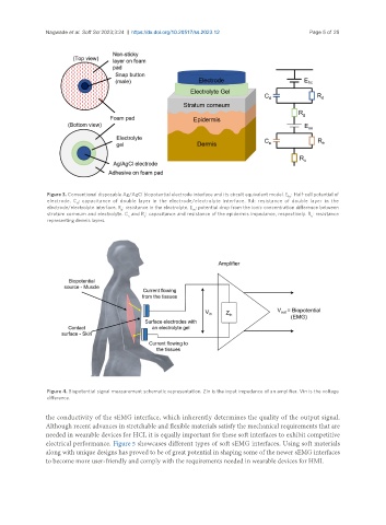
Figure 3. Conventional disposable Ag/AgCl biopotential electrode interface and its circuit equivalent model. E : Half-cell potential of
hc
electrode. C : capacitance of double layer in the electrode/electrolyte interface. Rd: resistance of double layer in the
d
electrode/electrolyte interface. R : resistance in the electrolyte. E : potential drop from the ionic concentration difference between
se
g
stratum corneum and electrolyte. C and R : capacitance and resistance of the epidermis impedance, respectively. R : resistance
e
e
u
representing dermis layers.
Figure 4. Biopotential signal measurement schematic representation. Zin is the input impedance of an amplifier. Vin is the voltage
difference.
the conductivity of the sEMG interface, which inherently determines the quality of the output signal.
Although recent advances in stretchable and flexible materials satisfy the mechanical requirements that are
needed in wearable devices for HCI, it is equally important for these soft interfaces to exhibit competitive
electrical performance. Figure 5 showcases different types of soft sEMG interfaces. Using soft materials
along with unique designs has proved to be of great potential in shaping some of the newer sEMG interfaces
to become more user-friendly and comply with the requirements needed in wearable devices for HMI.