
Page 308 - Read Online
P. 308
Torabinia et al. Mini-invasive Surg 2021;5:32 https://dx.doi.org/10.20517/2574-1225.2021.63 Page 7 of 12
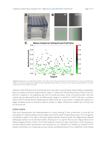
Figure 4. Validating 3D co-registration algorithm. (A) Image of 3D printed jig holding array of 50 metal spheres at various heights. (B)
Image of fluoroscopy images at two angles and auto-detection of those spheres. (C) Graph of error for each sphere based on true value
measured from 3D CAD file for bi-plane.
catheter is vital information for determining how a procedure was performed and providing a quantitative
basis for analysis and future improvements. Figure 7A shows the selected fluoroscopic frames (LAO56°,
RAO30°) acquired at the beginning and end of a mock procedure in the 3D printed model. After the
catheter tip was detected from the two fluoroscopic images (i.e., RAO30°, LAO56°), the tip's coordinate
(from LAO56°) and the derived transformation matrix (from Eq. 5) was used to co-register the catheter in a
single coordinate system as described earlier in section 2.5. Figure 7B shows the catheter tip's 3D trajectory
for the mock test.
CONCLUSION
This work demonstrates the implementation of a deep learning U-Net architecture to track the 3D
movement of a catheter during a mock cardiac intervention under bi-plane fluoroscopy. We leveraged an
end-diastolic cardiac CT in order to 3D print a patient-specific phantom model. We integrated four fiducial
radiopaque markers on the phantom model, allowing us to co-register fluoroscopic images taken at two
different angles (RAO30, LAO55). The U-Net model was trained in a supervised manner on the training set,
and the trained model's performance was evaluated on the validation set. Finally, we assessed the DL
model's performance by computing accuracy metrics and determining the Dice coefficient on the testing