
Page 40 - Read Online
P. 40
Page 346 Sellers et al. Intell Robot 2022;2(4):33354 I http://dx.doi.org/10.20517/ir.2022.21
Figure 8. Illustration of how the VHF uses a probability along with histogram-based grid to detect and build a map simultaneously.
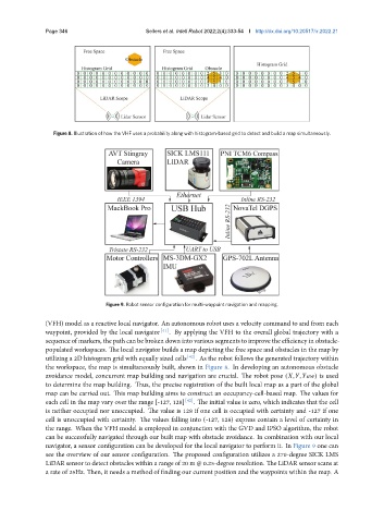
Figure 9. Robot sensor configuration for multi-waypoint navigation and mapping.
(VFH) model as a reactive local navigator. An autonomous robot uses a velocity command to and from each
waypoint, provided by the local navigator [41] . By applying the VFH to the overall global trajectory with a
sequence of markers, the path can be broken down into various segments to improve the efficiency in obstacle-
populated workspaces. The local navigator builds a map depicting the free space and obstacles in the map by
utilizing a 2D histogram grid with equally sized cells [42] . As the robot follows the generated trajectory within
the workspace, the map is simultaneously built, shown in Figure 8. In developing an autonomous obstacle
avoidance model, concurrent map building and navigation are crucial. The robot pose ( , , ) is used
to determine the map building. Thus, the precise registration of the built local map as a part of the global
map can be carried out. This map building aims to construct an occupancy-cell-based map. The values for
each cell in the map vary over the range [-127, 128] [42] . The initial value is zero, which indicates that the cell
is neither occupied nor unoccupied. The value is 128 if one cell is occupied with certainty and -127 if one
cell is unoccupied with certainty. The values falling into (-127, 128) express contain a level of certainty in
the range. When the VFH model is employed in conjunction with the GVD and IPSO algorithm, the robot
can be successfully navigated through our built map with obstacle avoidance. In combination with our local
navigator, a sensor configuration can be developed for the local navigator to perform it. In Figure 9 one can
see the overview of our sensor configuration. The proposed configuration utilizes a 270-degree SICK LMS
LiDAR sensor to detect obstacles within a range of 20 m @ 0.25-degree resolution. The LiDAR sensor scans at
a rate of 25Hz. Then, it needs a method of finding our current position and the waypoints within the map. A