
Page 44 - Read Online
P. 44
Page 350 Sellers et al. Intell Robot 2022;2(4):33354 I http://dx.doi.org/10.20517/ir.2022.21
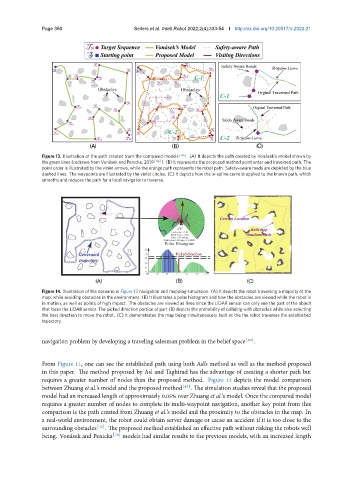
Figure 13. Illustration of the path created from the compared models [46] . (A) It depicts the path created by Vonásek’s model shown by
k
the green lines (redrawn from Vonásek and Pe nic a, 2019 [46] ). (B) It represents the proposed method point order and traversed path. The
point order is illustrated by the violet arrows, while the orange path represents the robot path. Safety-aware roads are depicted by the blue
dashed lines. The waypoints are illustrated by the violet circles. (C) It depicts how the B-spline curve is applied to the known path, which
smooths and reduces the path for a local navigator to traverse.
Figure 14. Illustration of the scenario in Figure 13 navigation and mapping simulation. (A) It depicts the robot traversing a majority of the
map, while avoiding obstacles in the environment. (B) It illustrates a polar histogram and how the obstacles are viewed while the robot is
in motion, as well as points of high impact. The obstacles are viewed as lines since the LiDAR sensor can only see the part of the object
that faces the LiDAR sensor. The picked direction portion of part (B) depicts the probability of colliding with obstacles while also selecting
the best direction to move the robot. (C) It demonstrates the map being simultaneously built as the the robot traverses the established
trajectory.
navigation problem by developing a traveling salesman problem in the belief space [44] .
From Figure 11, one can see the established path using both Asl’s method as well as the method proposed
in this paper. The method proposed by Asl and Taghirad has the advantage of creating a shorter path but
requires a greater number of nodes than the proposed method. Figure 12 depicts the model comparison
between Zhuang et al.’s model and the proposed method [45] . The simulation studies reveal that the proposed
model had an increased length of approximately 0.05% over Zhuang et al.’s model. Once the compared model
requires a greater number of nodes to complete its multi-waypoint navigation, another key point from this
comparison is the path created from Zhuang et al.’s model and the proximity to the obstacles in the map. In
a real-world environment, the robot could obtain server damage or cause an accident if it is too close to the
surrounding obstacles [45] . The proposed method established an effective path without risking the robots well
being. Vonásek and Penicka [46] models had similar results to the previous models, with an increased length