
Page 45 - Read Online
P. 45
Sellers et al. Intell Robot 2022;2(4):33354 I http://dx.doi.org/10.20517/ir.2022.21 Page 351
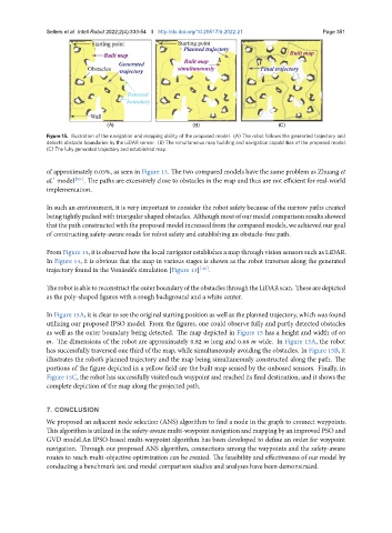
Figure 15. Illustration of the navigation and mapping ability of the proposed model. (A) The robot follows the generated trajectory and
detects obstacle boundaries by the LiDAR sensor. (B) The simultaneous map building and navigation capabilities of the proposed model.
(C) The fully generated trajectory and established map.
of approximately 0.05%, as seen in Figure 13. The two compared models have the same problem as Zhuang et
al.’ model [45] . The paths are excessively close to obstacles in the map and thus are not efficient for real-world
implementation.
In such an environment, it is very important to consider the robot safety because of the narrow paths created
beingtightlypackedwithtriangularshapedobstacles. Althoughmostofourmodelcomparisonresultsshowed
thatthe path constructed with theproposed model increased from the compared models, we achieved our goal
of constructing safety-aware roads for robot safety and establishing an obstacle-free path.
From Figure 14, it is observed how the local navigator establishes a map through vision sensors such as LiDAR.
In Figure 14, it is obvious that the map in various stages is shown as the robot traverses along the generated
trajectory found in the Vonásek’s simulation [Figure 13] [46] .
TherobotisabletoreconstructtheouterboundaryoftheobstaclesthroughtheLiDARscan. Thesearedepicted
as the poly-shaped figures with a rough background and a white center.
In Figure 15A, it is clear to see the original starting position as well as the planned trajectory, which was found
utilizing our proposed IPSO model. From the figures, one could observe fully and partly detected obstacles
as well as the outer boundary being detected. The map depicted in Figure 15 has a height and width of 60
. The dimensions of the robot are approximately 0.82 long and 0.68 wide. In Figure 15A, the robot
has successfully traversed one third of the map, while simultaneously avoiding the obstacles. In Figure 15B, it
illustrates the robot’s planned trajectory and the map being simultaneously constructed along the path. The
portions of the figure depicted in a yellow field are the built map sensed by the onboard sensors. Finally, in
Figure 15C, the robot has successfully visited each waypoint and reached its final destination, and it shows the
complete depiction of the map along the projected path.
7. CONCLUSION
We proposed an adjacent node selection (ANS) algorithm to find a node in the graph to connect waypoints.
Thisalgorithmisutilizedinthesafety-awaremulti-waypointnavigationandmappingbyanimprovedPSOand
GVD model.An IPSO-based multi-waypoint algorithm has been developed to define an order for waypoint
navigation. Through our proposed ANS algorithm, connections among the waypoints and the safety-aware
routes to reach multi-objective optimization can be created. The feasibility and effectiveness of our model by
conducting a benchmark test and model comparison studies and analyses have been demonstrated.