Page 38 - Read Online
P. 38

Page 344                       Sellers et al. Intell Robot 2022;2(4):333­54  I http://dx.doi.org/10.20517/ir.2022.21


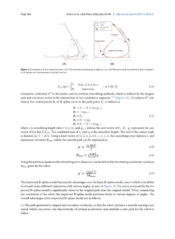
               Figure 7. Illustration of the B-spline function. (A) The improved segmented B-spline curve. (B) The same path smoothed by the fundamen-
               tal B-spline and the improved B-spline function.


                                                 {
                                                  1,              ≤    ≤      +1
                                              ,   (  ) =               ;    ∈ [0, 1]                  (13)
                                                  0,         ℎ            
               Geometric continuity    is the metric used to evaluate smoothing methods, which is defined by the tangent
                                   2
               unit and curvature vector at the intersection of two continuous segments [38]  [Figure 7A]. To achieve    con-
                                                                                                     2
               tinuity, the control points       of B-spline curve to the path point,       , is defined as

                                                      1 =       − (1 +   )   2      −1
                                                      2 = −   2      −1
                                                                                                      (14)
                                                      3 =      
                                                      4 =       +    2      
                                                      5 =       + (1 +   )   2      −1
               where    is smoothing length ratio    =    1 /   2, and      −1 defines the unit vector of      −1       .       represents the unit
               vector of the line            +1. The combined sum of    1 and    2 is the smoothed length. The half of the corner angle
               is denoted as: Γ =   /2. Using a knot vector of [0, 0, 0, 0, 0.5, 1, 1, 1, 1], the smoothing error distance    and
               maximum curvature           within the smooth path can be expressed as:

                                                               2 sin Γ
                                                         =                                            (15)
                                                               2
                                                               =  4 sin Γ                             (16)
                                                                  2
                                                             3   2 cos Γ
               Usingthepreviousequationsthesmoothingerrordistance    canbedefinedbytheexistingmaximumcurvature
                         given by the robot:

                                                                2
                                                         =  2 tan Γ                                   (17)
                                                            3         
               The improved B-spline model has specific advantages over the basic B-spline model, one of which is its ability
               to smooth many different trajectories with various angles, as seen in Figure 7B. The curve produced by the im-
               proved B-spline model is significantly closer to the original path than the original model. When considering
               the constraints of the robot, the improved B-spline mode performs better in various degrees of angles. The
               overall advantages of the improved B-spline model are as follows:

               (1) The path generated is tangent and curvature continuity, so that the robot can have a smooth steering com-
               mand, which can correct any discontinuity of normal acceleration and establish a safer path for the robot to
               follow.
   33   34   35   36   37   38   39   40   41   42   43