
Page 100 - Read Online
P. 100
Page 94 Li et al. Intell Robot 2022;2(1):89–104 I http://dx.doi.org/10.20517/ir.2022.02
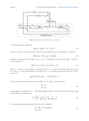
Figure 3. Scheme of open-closed-loop PD-type ILC system.
(2) Defining the operator yields
® ¯
® ¯ ®
(® )( ) = (® )( ), ∀® ∈ [0, ] (12)
where ® ∈ [0, ] is the only solution to the first outcome, and there exists a constant 1 > 0 subject to:
( ∫ )
® ¯ (13)
k (® )( )k ≤ 1 + k® ( )kd
0
®
Lemma 2. Assuming that the sequence { } ≥0, ≥ 0, converges to zero, the operator : [0, ] →
[0, ] will meet
( ∫ )
® (14)
k (® )( )k ≤ + k ® ( )kd +
0
where > 0 and ≥ 1 are constants. Assuming that ( ) is a × continuous function matrix, the operator
: [0, ] → [0, ] satisfies (® )( ) = ( ) ® ( ). If < 1, being the spectral radius of , for ∀ ∈ [0, ],
®
®
®
there exists
®
®
®
®
®
lim ( + n )( + −1 ) · · · ( + 0 )(® )( ) = 0
®
→∞
®
For the parallel robot under study, the state variables = [® 1 , ® 2 ] T are defined below:
8×1
{
® 1 = ®
(15)
® 2 = ® ¤
Accordingly, the variable ( , ) 4×1 = − ( ® )( ( ® , ® ¤ ) ® ¤ + ( ® )) can be defined; thus, the dynamic model
−1
®
®
®
of the system can be expressed as:
[ ] [ ] [ ]
® ¤
® ¤ 1 0
® ¤
= = + −1 (16)
( , )
® ¤ 2 ® ® ( ® ) ® ( )
As a consequence, the state equation of the robot can be obtained:
{
® ¤ ® ®
= ( , ) + ( ® , ® ¤ ) ® ( )
(17)
=
®
®