
Page 76 - Read Online
P. 76
Yang et al. Intell Robot 2024;4(1):107-24 I http://dx.doi.org/10.20517/ir.2024.07 Page 115
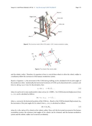
Hip joint
Support joint
Knee joint
Ankle joint
wheel 2
wheel 1
wheel 4
wheel 3
Figure 5. The simulation model of the HEW system. HEW: Human-exoskeleton-walker.
z z z z 2
Y Y Y 4
x x x x
1
3
Figure 6. The wheels of the robotic walker.
and the robotic walker. Therefore, the question is how to control these wheels to drive the robotic walker to
coordinately follow the movement of the human-exoskeleton system.
Based on Equation (1), the movement of the COM during walking can be calculated with the joint angles of
the exoskeleton robot. Additionally, the horizontal movement of COM can be discretized with a constant unit
time Δ , taking as an index for discretization, then
= Δ · , = 0, 1, 2, . . . (13)
where Δ can be set to some small positive value such as Δ = 0.005 s. The COM horizontal displacement from
−1 to can be calculated as follows:
Δ = − −1 , = 1, 2, . . . (14)
where represents the horizontal position of the COM at . Based on the COM horizontal displacement Δ ,
the increment of the joint angles for the wheels from −1 to is calculated as follows:
Δ = Δ / , (15)
where is the radius of the wheels on the robotic walker. Now, with the horizontal movement of the human-
exoskeleton system, the reference joint angles of the wheels can be obtained, and the human-exoskeleton
system and the robotic walker can be moved coordinately.