
Page 72 - Read Online
P. 72
Yang et al. Intell Robot 2024;4(1):107-24 I http://dx.doi.org/10.20517/ir.2024.07 Page 111
Base frame
Cantilever
Thigh
Shank
Foot
Support joint
Hip joint
Knee joint
z Ankle joint
x
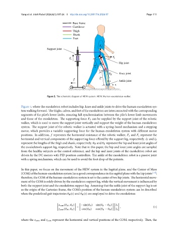
Figure 3. The schematic diagram of HEW system. HEW: Human-exoskeleton-walker.
Figure 3, where the exoskeleton robot includes hip, knee and ankle joints to drive the human-exoskeleton sys-
temwalkingforward. Thethighs, calves, andfeetoftheexoskeletonareinterconnectedwiththecorresponding
segments of the pilot’s lower limbs, ensuring full synchronization between the pilot’s lower limb movements
and those of the exoskeleton. The supporting force can be supplied by the support joint of the robotic
walker, which is used to move the support joint vertically and support the weight of the human-exoskeleton
system. The support joint of the robotic walker is actuated with a spring-based mechanism and a stepping
motor, which provides a variable supporting force for the human-exoskeleton system with different motor
positions. In addition, represents the horizontal resistance of the robotic walker; and represent the
horizontal and vertical components of the supporting force offered by the support leg, respectively. and
represent the lengths of the thigh and shank, respectively. and represent the hip and knee joint angles of
the exoskeleton’s support leg, respectively. Note that in this paper, the hip and knee joint angles are sampled
from the healthy subjects as the control reference, and the hip and knee joints of the exoskeleton robot are
driven by the DC motors with PID position controllers. The ankle of the exoskeleton robot is a passive joint
with a spring mechanism, which can be used to avoid the foot drop of the patients.
In this paper, we focus on the movement of the HEW system in the Sagittal plane, and the Center of Mass
(COM)ofthehuman-exoskeletonsystemhasagoodcorrespondenceinthesagittalplanewiththehipjoints [19] ;
therefore,theCOMofthehuman-exoskeletonsystemissettothecenteroftwohipjoints. Thehorizontalmove-
ment of the COM is solely driven by the exoskeleton support leg, while the vertical movement is influenced by
both the support joint and the exoskeleton support leg. Assuming that the ankle joint of the support leg is set
as the origin of the Cartesian frame, the COM’s position of the human-exoskeleton system can be described
when the predefined gait trajectories ( ) and ( ) are employed to drive the exoskeleton:
[ ] [ ] [ ]
com ( , ) − sin( ) sin( − )
= , (1)
com ( , ) cos( ) cos( − )
where the com and com represent the horizontal and vertical positions of the COM, respectively. Then, the