
Page 59 - Read Online
P. 59
Tong et al. Intell Robot 2024;4:125-45 I http://dx.doi.org/10.20517/ir.2024.08 Page 137
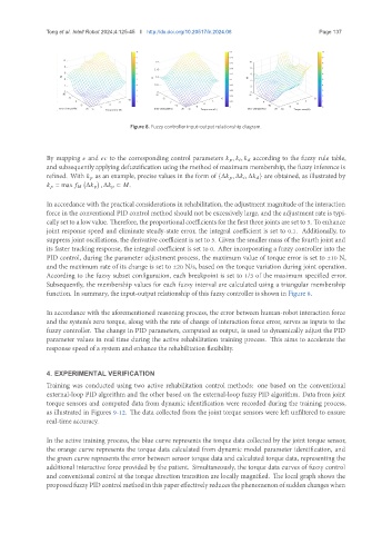
Figure 8. Fuzzy controller input-output relationship diagram.
By mapping and to the corresponding control parameters , , according to the fuzzy rule table,
and subsequently applying defuzzification using the method of maximum membership, the fuzzy inference is
refined. With as an example, precise values in the form of {Δ , Δ , Δ } are obtained, as illustrated by
= max Δ p , Δ p ⊂ .
In accordance with the practical considerations in rehabilitation, the adjustment magnitude of the interaction
force in the conventional PID control method should not be excessively large, and the adjustment rate is typi-
cally set to a low value. Therefore, the proportional coefficients for the first three joints are set to 5. To enhance
joint response speed and eliminate steady-state error, the integral coefficient is set to 0.1. Additionally, to
suppress joint oscillations, the derivative coefficient is set to 5. Given the smaller mass of the fourth joint and
its faster tracking response, the integral coefficient is set to 0. After incorporating a fuzzy controller into the
PID control, during the parameter adjustment process, the maximum value of torque error is set to ±10 N,
and the maximum rate of its change is set to ±20 N/s, based on the torque variation during joint operation.
According to the fuzzy subset configuration, each breakpoint is set to 1/3 of the maximum specified error.
Subsequently, the membership values for each fuzzy interval are calculated using a triangular membership
function. In summary, the input-output relationship of this fuzzy controller is shown in Figure 8.
In accordance with the aforementioned reasoning process, the error between human-robot interaction force
and the system’s zero torque, along with the rate of change of interaction force error, serves as inputs to the
fuzzy controller. The change in PID parameters, computed as output, is used to dynamically adjust the PID
parameter values in real time during the active rehabilitation training process. This aims to accelerate the
response speed of a system and enhance the rehabilitation flexibility.
4. EXPERIMENTAL VERIFICATION
Training was conducted using two active rehabilitation control methods: one based on the conventional
external-loop PID algorithm and the other based on the external-loop fuzzy PID algorithm. Data from joint
torque sensors and computed data from dynamic identification were recorded during the training process,
as illustrated in Figures 9-12. The data collected from the joint torque sensors were left unfiltered to ensure
real-time accuracy.
In the active training process, the blue curve represents the torque data collected by the joint torque sensor,
the orange curve represents the torque data calculated from dynamic model parameter identification, and
the green curve represents the error between sensor torque data and calculated torque data, representing the
additional interactive force provided by the patient. Simultaneously, the torque data curves of fuzzy control
and conventional control at the torque direction transition are locally magnified. The local graph shows the
proposedfuzzyPIDcontrolmethodinthispapereffectivelyreducesthephenomenonofsuddenchangeswhen