
Page 15 - Read Online
P. 15
Page 340 Zhang et al. Intell. Robot. 2025, 5(2), 333-54 I http://dx.doi.org/10.20517/ir.2025.17
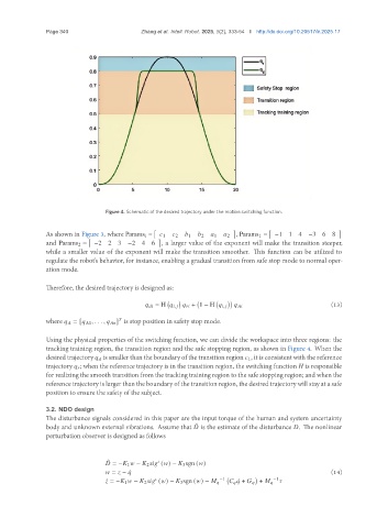
Figure 4. Schematic of the desired trajectory under the motion switching function.
As shown in Figure 3, where Params i = 1 2 1 2 1 2 , Params 1 = −1 1 4 −3 6 8
and Params 2 = −2 2 3 −2 4 6 , a larger value of the exponent will make the transition steeper,
while a smaller value of the exponent will make the transition smoother. This function can be utilized to
regulate the robot’s behavior, for instance, enabling a gradual transition from safe stop mode to normal oper-
ation mode.
Therefore, the desired trajectory is designed as:
= H , + 1 − H , (13)
where = [ 1 , . . . , ] is stop position in safety stop mode.
Using the physical properties of the switching function, we can divide the workspace into three regions: the
tracking training region, the transition region and the safe stopping region, as shown in Figure 4. When the
desired trajectory is smaller than the boundary of the transition region 1, it is consistent with the reference
trajectory ; when the reference trajectory is in the transition region, the switching function is responsible
for realizing the smooth transition from the tracking training region to the safe stopping region; and when the
reference trajectory is larger than the boundary of the transition region, the desired trajectory will stay at a safe
position to ensure the safety of the subject.
3.2. NDO design
The disturbance signals considered in this paper are the input torque of the human and system uncertainty
body and unknown external vibrations. Assume that is the estimate of the disturbance . The nonlinear
ˆ
perturbation observer is designed as follows
ˆ
= − 1 − 2 ( ) − 3 sgn ( )
= − ¤ (14)
−1 −1
¤ = − 1 − 2 ( ) − 3 sgn ( ) − ¤ + + 