
Page 14 - Read Online
P. 14
Zhang et al. Intell. Robot. 2025, 5(2), 333-54 I http://dx.doi.org/10.20517/ir.2025.17 Page 339
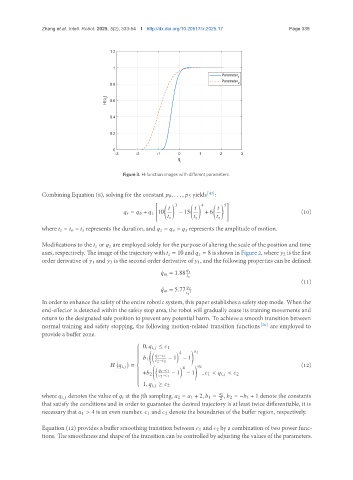
Figure 3. H-function images with different parameters.
Combining Equation (8), solving for the constant 0 , . . . , 5 yields [43] :
" #
3 4 5
= + 10 − 15 + 6 (10)
where = − represents the duration, and = − represents the amplitude of motion.
Modifications to the or are employed solely for the purpose of altering the scale of the position and time
axes, respectively. The image of the trajectory with = 10 and = 8 is shown in Figure 2, where 2 is the first
order derivative of 1 and 3 is the second order derivative of 1, and the following properties can be defined:
¤ = 1.88
(11)
¥ = 5.77
2
In order to enhance the safety of the entire robotic system, this paper establishes a safety stop mode. When the
end-effector is detected within the safety stop area, the robot will gradually cease its training movements and
return to the designated safe position to prevent any potential harm. To achieve a smooth transition between
normal training and safety stopping, the following motion-related transition functions [30] are employed to
provide a buffer zone.
0, , ≤ 1
4 1
− 1
− 1 − 1
1
2 − 1
, = 4 2 (12)
− 1
− 1 − 1
+ 2 , 1 < , < 2
2 − 1
1, , ≥ 2
where , denotes the value of at the jth sampling, 2 = 1 + 2, 1 = 2 , 2 = − 1 + 1 denote the constants
2
that satisfy the conditions and in order to guarantee the desired trajectory is at least twice differentiable, it is
necessary that 1 > 4 is an even number. 1 and 2 denote the boundaries of the buffer region, respectively.
Equation (12) provides a buffer smoothing transition between 1 and 2 by a combination of two power func-
tions. The smoothness and shape of the transition can be controlled by adjusting the values of the parameters.