
Page 20 - Read Online
P. 20
Zhang et al. Intell. Robot. 2025, 5(2), 333-54 I http://dx.doi.org/10.20517/ir.2025.17 Page 345
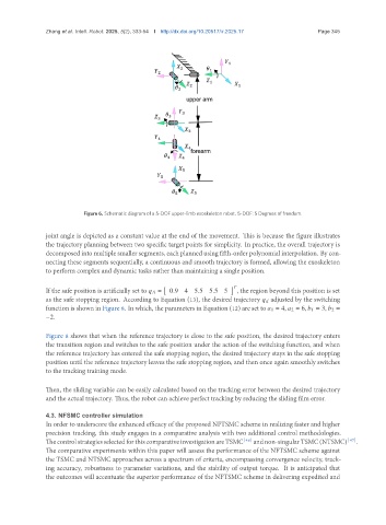
Figure 6. Schematic diagram of a 5-DOF upper-limb exoskeleton robot. 5-DOF: 5 Degrees of freedom.
joint angle is depicted as a constant value at the end of the movement. This is because the figure illustrates
the trajectory planning between two specific target points for simplicity. In practice, the overall trajectory is
decomposed into multiple smaller segments, each planned using fifth-order polynomial interpolation. By con-
necting these segments sequentially, a continuous and smooth trajectory is formed, allowing the exoskeleton
to perform complex and dynamic tasks rather than maintaining a single position.
If the safe position is artificially set to = 0.9 4 5.5 5.5 5 , the region beyond this position is set
as the safe stopping region. According to Equation (13), the desired trajectory adjusted by the switching
function is shown in Figure 8. In which, the parameters in Equation (12) are set to 1 = 4, 2 = 6, 1 = 3, 2 =
−2.
Figure 8 shows that when the reference trajectory is close to the safe position, the desired trajectory enters
the transition region and switches to the safe position under the action of the switching function, and when
the reference trajectory has entered the safe stopping region, the desired trajectory stays in the safe stopping
position until the reference trajectory leaves the safe stopping region, and then once again smoothly switches
to the tracking training mode.
Then, the sliding variable can be easily calculated based on the tracking error between the desired trajectory
and the actual trajectory. Thus, the robot can achieve perfect tracking by reducing the sliding film error.
4.3. NFSMC controller simulation
In order to underscore the enhanced efficacy of the proposed NFTSMC scheme in realizing faster and higher
precision tracking, this study engages in a comparative analysis with two additional control methodologies.
ThecontrolstrategiesselectedforthiscomparativeinvestigationareTSMC [46] andnon-singularTSMC(NTSMC) [47] .
The comparative experiments within this paper will assess the performance of the NFTSMC scheme against
the TSMC and NTSMC approaches across a spectrum of criteria, encompassing convergence velocity, track-
ing accuracy, robustness to parameter variations, and the stability of output torque. It is anticipated that
the outcomes will accentuate the superior performance of the NFTSMC scheme in delivering expedited and