
Page 54 - Read Online
P. 54
Page 8 of 16 Wang et al. Intell Robot 2023;3(3):479-94 I http://dx.doi.org/10.20517/ir.2023.26
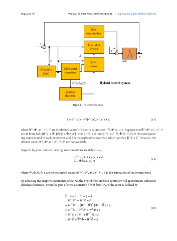
Figure 3. The control structure.
∗
∗
∗
∗
= + = Φ ( , , ) + , (17)
∗
∗
where , Φ , , , arethedesiredvaluesofnetworkparameters- , Φ, , , . Supposethat , Φ , , , ∗
∗
∗
∗
∗
∗
∗
∗
∗
∗
are all bounded, k k ≤ , kΦ k ≤ Φ, k k ≤ ¯ , k k ≤ ¯ , and k k ≤ ¯. , Φ, ¯ , ¯ , ¯ are the correspond-
¯ ¯
¯
¯
∗
∗
∗
∗
∗
ing upper bound of each parameter, and is the approximation error, which satisfies k k ≤ . However, the
¯
∗
desired values , Φ , , , , are not available.
∗
∗
∗
∗
∗
∗
Inspired by pure-motion tracking, some notations are defined as ,
( ) = ( ) + ( ) + ˆ (18)
ˆ ˆ ˆ
= Φ( ˆ , ˆ , ˆ )
where , Φ, ˆ , ˆ , ˆ are the estimated values of , Φ , , , . is the estimation of the system error.
ˆ ˆ
ˆ
∗
∗
∗
∗
∗
By adjusting the adaptive parameters of RNNs, the hybrid motion/force controller will approximate unknown
dynamic functions. From the part of error estimation = Φ( ˆ , ˆ , ˆ), the error is defined by
ˆ
ˆ ˆ
ˆ
= − = + − ˆ
∗
e
∗
ˆ ˆ
= Φ − Φ +
∗
∗
˜
= Φ − − Φ − Φ + , (19)
∗
∗
∗
e
e
= Φ − Φ + Φ +
∗
e e
∗ e
e
e ˆ
= Φ + + Φ +
ˆ e
e ˆ
= Φ + Φ + Φ +
˜ e
ˆ e