
Page 58 - Read Online
P. 58
Page 12 of 16 Wang et al. Intell Robot 2023;3(3):479-94 I http://dx.doi.org/10.20517/ir.2023.26
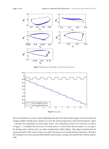
Figure 5. Phase diagram of joint angle and joint angular velocity ¤ .
Figure 6. Energy plot.
show that satisfactory excessive controlchattering exists due to the fault of mass change. It can be seen that the
designed adaptive sliding mode controller can meet the tracking requirement of the desired trajectory. Figure
11 describes the comparisons of system input torque. The comparisons of joint errors with time are shown
in Figure 12. It indicates that the joint error finally tends to 0, which shows that the system can converge to
the sliding surface and the robot can realize asymptotically stable walking. These figures illustrate that the
proposed adaptive SMC control system can achieve the purpose of tracking reference trajectories. Therefore,
the tracking errors of the proposed RNN hybrid control system converge more quickly than without adaptive
SMC.