
Page 51 - Read Online
P. 51
Wang et al. Intell Robot 2023;3(3):479-94 I http://dx.doi.org/10.20517/ir.2023.26 Page 5 of 16
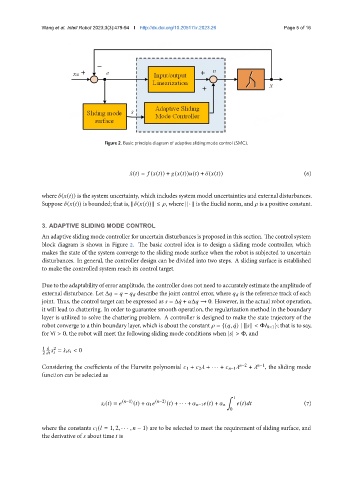
Figure 2. Basic principle diagram of adaptive sliding mode control (SMC).
¤ ( ) = ( ( )) + ( ( )) ( ) + ( ( )) (6)
where ( ( )) is the system uncertainty, which includes system model uncertainties and external disturbances.
Suppose ( ( )) is bounded; that is, k ( ( ))k ≤ , where k · k is the Euclid norm, and is a positive constant.
3. ADAPTIVE SLIDING MODE CONTROL
An adaptive sliding mode controller for uncertain disturbances is proposed in this section. The control system
block diagram is shown in Figure 2. The basic control idea is to design a sliding mode controller, which
makes the state of the system converge to the sliding mode surface when the robot is subjected to uncertain
disturbances. In general, the controller design can be divided into two steps. A sliding surface is established
to make the controlled system reach its control target.
Due to the adaptability of error amplitude, the controller does not need to accurately estimate the amplitude of
external disturbance. Let Δ = − describe the joint control error, where is the reference track of each
joint. Thus, the control target can be expressed as = Δ ¤ + Δ → 0. However, in the actual robot operation,
it will lead to chattering. In order to guarantee smooth operation, the regularization method in the boundary
layer is utilized to solve the chattering problem. A controller is designed to make the state trajectory of the
robot converge to a thin boundary layer, which is about the constant = {( , ¤) | k k < Φ 8×1 }; that is to say,
for ∀ > 0, the robot will meet the following sliding mode conditions when | | > Φ, and
1 d 2
= ¤ < 0
2
Considering the coefficients of the Hurwitz polynomial 1 + 2 + · · · + −1 −2 + −1 , the sliding mode
function can be selected as
¹
( ) = ( −1) ( ) + 1 ( −2) ( ) + · · · + −1 ( ) + ( ) (7)
0
where the constants ( = 1, 2, · · · , − 1) are to be selected to meet the requirement of sliding surface, and
the derivative of about time is