
Page 41 - Read Online
P. 41
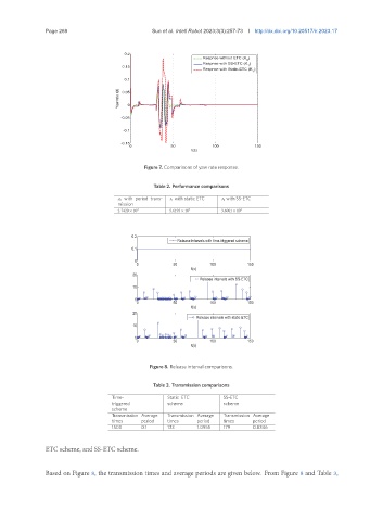
Page 268                         Sun et al. Intell Robot 2023;3(3):257-73  I http://dx.doi.org/10.20517/ir.2023.17


                                                                5HVSQVH ZLWKRXW (7&  .

                                                                5HVSQVH ZLWK 66 (7&  .

                                                                5HVSQVH ZLWK 6WDWLF (7&  .


                                      <DZ UDWH U W


                                                             W V
                                              Figure 7. Comparisons of yaw rate response.


                                                 Table 2. Performance comparisons
                                         0 with period trans-     1 with static ETC     2 with SS-ETC
                                      mission
                                      2.7420 × 10 3   5.6193 × 10 3   3.6061 × 10 3


                                                        5HOHDVH LQWHUYDOV ZLWK WLPH WULJJHUHG VFKHPH


                                                             W V

                                                               5HOHDVH LQWHUYDOV ZLWK 66 (7&


                                                             W V

                                                              5HOHDVH LQWHUYDOV ZLWK VWDWLF (7&


                                                             W V


                                                Figure 8. Release interval comparisons.

                                                 Table 3. Transmission comparisons

                                    Time-            Static ETC       SS-ETC
                                    triggered        scheme           scheme
                                    scheme
                                    Transmission Average  Transmission Average  Transmission Average
                                    times    period  times    period  times     period
                                    1500     0.1     133      1.0955  179       0.8346


               ETC scheme, and SS-ETC scheme.


               Based on Figure 8, the transmission times and average periods are given below. From Figure 8 and Table 3,