
Page 39 - Read Online
P. 39
Page 266 Sun et al. Intell Robot 2023;3(3):257-73 I http://dx.doi.org/10.20517/ir.2023.17
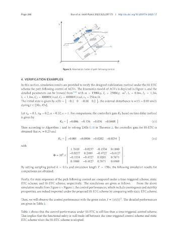
Figure 3. Kinematics model of path following control.
4. VERIFICATION EXAMPLES
In this section, simulation results are provided to verify the designed stabilization method under the SS-ETC
scheme for path following control of AGVs. The kinematics model of AGVs is depicted in Figure 3, and the
detailed parameters can be browed from [32] with = 1500 , = 2500 · , = 0.8 , = 1.3 ,
2
= 1.4 , = 40000 / , = 40000 / , = 25 /ℎ.
[ ]
The initial state is given by (0) = −0.1 0 −0.01 0.2 , the external disturbance is ( ) = 0.01 sin( )
during ∈ [30 , 45 ].
Let = 0.1, = 0.2, = 0.32, = 1. For comparisons, the controller’s gain 0 based on time delay method
is given by
[ ]
0 = −0.006 −0.136 −0.036 −0.0408 (15)
Then according to Algorithm 1 and by solving LMIs (13) in Theorem 2, the controller gain for SS-ETC is
obtained that = 0.23 and
[ ]
1 = −0.001 −0.0806 −0.0202 −0.0254 (16)
with
1.7610 −0.0237 −0.1534 0.1880
8 −0.0237 0.2489 −0.4727 −0.4127
Φ = 10 × .
−0.1534 −0.4727 0.9203 0.7671
0.1880 −0.4127 0.7671 0.6969
By setting sampling period ℎ = 0.1 and simulation length = 150 , the following simulation results for
comparisons are obtained.
Firstly, the state responses of the path following control are compared under a time-triggered scheme, static
ETC scheme, and SS-ETC scheme, respectively. The simulations are given as follows. From the above
simulation results from Figure 4 ∼ Figure 7, the control performances, which include convergence and stability
prosperities, are indeed improved under the proposed SS-ETC scheme by comparing with static ETC scheme.
Then, we will observe the control performance with the given index = || ( )|| . The detailed performances
2
are given in Table 2.
Table 2 shows that the control performance under SS-ETC is still less than a time-triggered control scheme.
This implies that the functional safety is well trade-off between the time-triggered control scheme and static
ETC scheme when the SS-ETC scheme is adopted.