
Page 34 - Read Online
P. 34
Sun et al. Intell Robot 2023;3(3):257-73 I http://dx.doi.org/10.20517/ir.2023.17 Page 261
66 (7& VFKHPH
<HV (QFRXUDJH 'HFUHDVH WKH
,V LW IDU DZD\ WUDQVPLVVLRQV WKUHVKROG
IURP UHIHUHQFHG
3K\VLFDO VWDWH VLJQDO " 6XSSUHVV ,QFUHDVH WKH (YHQW WKUHVKROG
1R WUDQVPLVVLRQV WKUHVKROG
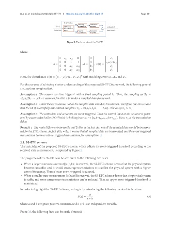
Figure 2. The basic idea of the SS-ETC.
where
0 0
0
1
0 0 0 1 0 − ( )
= , = , ( ) =
0 0 11 12 1 2
0 0 21 22 2 3
Here, the disturbance ( ) = [ 1 , − ( ) , 2 , 3 ] with modeling errors 1, 2, and 3.
For the purpose of achieving a better understanding of the proposed SS-ETC framework, the following general
assumptions are given first.
Assumption 1 The sensors are time triggered with a fixed sampling period ℎ. Then, the sampling set S 1 =
{0, ℎ, 2ℎ, · · · , ℎ} is assumed for all ∈ N under a sampled-data framework.
Assumption 2 UndertheETCscheme, notallthesampleddatawouldbetransmitted. Therefore, onecanassume
that the set of successfully transmitted samples is S 2 = {0, 1 ℎ, 2 ℎ, · · · , ℎ}. Obviously, S 2 ⊆ S 1.
Assumption 3 The controllers and actuators are event-triggered. Then the control input at the actuator is gener-
isthetransmission
atedbyazero-orderholder(ZOH)withitsholdinginterval ∈ [ ℎ+ , +1 ℎ+ +1 ). Here,
delay.
Remark 1 The main difference between S 1 and S 2 lies in the fact that not all the sampled data would be transmit-
ted for the ETC scheme. In fact, if S 1 = S 2, it means that all sampled data are transmitted, and the event-triggered
transmission becomes a time-triggered transmission for Assumption. 2.
2.2. SS-ETC scheme
The basic idea of the proposed SS-ETC scheme, which adjusts its event-triggered threshold according to the
received state measurement, is captured by Figure 2.
The properties of the SS-ETC can be attributed to the following two cases:
• When a larger state measurement || ( ℎ)|| is received, the SS-ETC scheme deems that the physical system
becomes unstable, and it would encourage transmissions to stabilize the physical system with a higher
control frequency. Then a lower event-triggered is adopted.
• Whenasmallerstatemeasurement || ( ℎ)|| isreceived, theSS-ETCschemedeemsthatthephysicalsystem
is stable, and some unnecessary transmissions can be reduced. Then an upper event-triggered threshold is
maintained.
In order to highlight the SS-ETC scheme, we begin by introducing the following barrier-like function:
( ) = (3)
+
where and are given positive constants, and ≥ 0 is an independent variable.
From (3), the following facts can be easily obtained: