
Page 224 - Read Online
P. 224
Page 8 of 14 Kautsar et al. Energy Mater. 2025, 5, 500129 https://dx.doi.org/10.20517/energymater.2025.26
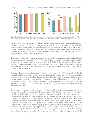
Figure 4. (A) Electrical conductivity (σ ) and (B) total thermal conductivity (κ) and lattice thermal conductivity (κ ) of the HP, HD, and
lat
xx
RE-Cu (RE = Dy-Nd, Nd, Pr) GBDP HD magnets. HP: Hot-pressed; HD: hot-deformed; GBDP: grain boundary diffusion process.
Supplementary Table 2. The estimated values of Π and S are summarized in Figure 6D. The Π (S )
ANE
AEE
ANE
AEE
increases from -7.9 × 10 V (-2.6 × 10 VK ) in the HP state to -1.3 × 10 V (-4.4 × 10 VK ) after HD.
-5
-7
-7
-1
-1
-4
-7
-4
-1
Further GBDP using Dy-Nd-Cu results in additional increments, reaching to -1.5 × 10 V (-5.0 × 10 VK ).
It is worth noting that, due to the crystallographic texture formed during hot-deformation, the transverse
thermopower at the M state (zero H) in HD and RE-Cu (RE = Dy-Nd, Nd, and Pr) GBDP Nd-Fe-B
r
magnets is nearly identical (85%-86%) to that of S .
ANE
The transverse thermoelectric conversion performance of ANE was evaluated using the dimensionless
[45]
figure of merit, z T, expressed as . As shown in Figure 6E, z T increases significantly after HD,
ANE
ANE
primarily due to the substantial rise in S . However, while GBDP further enhances S , the concurrent
ANE
ANE
increase in κ partially counterbalanced this improvement, resulting in slight increment in z T for the
ANE
Dy-Nd-Cu and Pr-Cu GBDP magnets. The highest z T value achieved in this study is 8.1 × 10 , observed
-6
ANE
in the Nd-Cu GBDP magnet.
α ≡ S + S
S can be decomposed into two components: S = ρ α - ρ AHE xx I II [6,28] . Here, ρ (= 1/σ ) is the
ANE
xx
xx xy
xx
ANE
longitudinal electrical resistivity, α is the transverse thermoelectric conductivity, ρ is the anomalous Hall
AHE
xy
resistivity, and α is the longitudinal thermoelectric conductivity. The S component reflects the direct
I
xx
conversion of a temperature gradient into a transverse electric field through α . In contrast, the S II
xy
component represents the transverse electric field due to the Seebeck-effect-induced carrier flow bent by
anomalous Hall effect (AHE). S can be rewritten as S = = -tanθ S , where θ is the
AHE xx
AHE
II
II
anomalous Hall angle.
The S values of the studied magnets are shown in Figure 7A. All the magnets exhibit negative S values,
xx
xx
with the absolute values decreasing after HD and subsequent GBDP. Figure 7B shows the ρ as a function of
yx
the H for the studied magnets. It is worth mentioning that the ρ curve follows the magnetization curves of
yx
the magnets and the slope of ρ as a function of external magnetic field becomes negligible after saturation
yx
of magnetization [Figure 7B]. This suggests that the ordinary Hall contribution to the ρ is negligible
yx
compared to anomalous Hall contribution in the present study . Additionally, the graph exhibits H-odd
[58]
symmetry characteristic, as it is symmetric with respect to the origin. This indicates that the
magneto-Seebeck effect also contributes negligibly. The ρ is determined by extrapolating ρ at μ H = 14 T
AHE
0
yx
to the zero field. Supplementary Figure 5 presents the ρ values and the anomalous Hall angle (tanθ ) of
AHE
AHE
the studied magnets. The absolute values of ρ and tanθ are gradually decreased after GBDP. Notably,
AHE
AHE
although ρ slightly decreases after HD, tanθ increases. Further studies are required to clarify the
AHE
AHE