
Page 187 - Read Online
P. 187
Page 12 of 14 Wang et al. Energy Mater 2023;3:300040 https://dx.doi.org/10.20517/energymater.2023.28
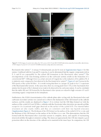
Figure 7. STEM images of cycled electrodes after 100 cycles: (A) LCO and (B) NCM811 electrodes using fluorinated ether electrolytes;
STEM images of cycled (C) LCO and (D) NCM811 electrodes using carbonate electrolytes.
fluorinated ether system . A unique N element peak can also be seen in Supplementary Figure 5 for this
[14]
system. Combined with the S 2p and N 1s spectra, it can be determined that the organic components rich in
F, S, and N are responsible for the robust SEI formation in the fluorinated ether system . The
[29]
decomposition of the film-forming additives in the carbonate system results in the formation of a
[7]
conventional SEI . Although there is a certain amount of S signal due to the reduction of the additive PS, it
is relatively weak compared to that obtained in the fluorinated ether system . Figure 6C and D presents the
[30]
XPS spectra of the cycled NCM811. It is worth noting that there is a unique CF peak in the C 1s spectrum
x
of the fluorinated ether system. At the same time, there is a strong peak from C-SO in the fluorinated ether
x
system, but the peak of the S element is too weak to be detected in the carbonate system. It can be concluded
that the stable SEI and CEI formed by the fluorinated ether system are related to high contents of F and S
containing organic components in the interphases.
Furthermore, the STEM characterization of the cathode plates after cycling with the fluorinated ether and
carbonate electrolyte systems was carried out to observe the thicknesses of the CEI formed on the cathode
surfaces, and the results are displayed in Figure 7. It is evident that the CEI films formed on both the
surfaces of the cycled LCO and NCM811 cathodes with the fluorinated ether electrolyte are smooth and flat,
except for the occasional small gaps observed on the surface of the cycled LCO. The internal lattice
structures are also clearly visible, and they are consistent with their raw layered structures
[Supplementary Figure 6]. The thickness of the CEI formed on the surface of the cycled LCO is 2.5 nm, and
the thickness of the CEI formed on the surface of the NCM811 is 6.5 nm. This demonstrates that the CEI
formed with the fluorinated ether electrolyte system is complete, dense, and capable of maintaining
structural stability throughout extended cycling. The dense yet appropriately thin CEI also imparts a good
protection effect on the structure of the cathode active material in the inner layer. In comparison, the CEI