
Page 47 - Read Online
P. 47
Teng et al. Microstructures 2023;3:2023019 https://dx.doi.org/10.20517/microstructures.2023.07 Page 11 of 29
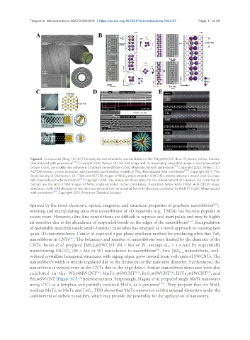
Figure 5. Compounds filling: (A) ACTEM analysis and schematic representation of the PbI @SWCNT. Blue: Pb atoms; yellow: I atoms
2
[109]
(Reproduced with permission . Copyright 2013, Wiley). (B) HRTEM image and corresponding simulation image of an encapsulated
[53]
bilayer CsSnI perovskite-like polymeric structure derived from CsSnI (Reproduced with permission . Copyright 2023, Wiley). (C)
3 3
[106]
ACTEM photos, crystal structure, and geometric optimization models of PtS (Reproduced with permission . Copyright 2017, The
2
Royal Society of Chemistry). (D) TEM and ACTEM images of NbSe single strand in DWCNTs, atomic structure model (red: Se, blue:
3
[51]
Nb) (Reproduced with permission . Copyright 2018, The American Association for the Advancement of Science). (E) From top to
bottom are the ADF-STEM images of MTe single-stranded carbon nanotubes. Illustration below ADF-STEM: ADF-STEM image
3
simulation (left) with the appropriate microscope condition noise added from the structure calculated by the DFT (right) (Reproduced
[50]
with permission . Copyright 2021, American Chemical Society).
Spurred by the novel electronic, optical, magnetic, and structural properties of graphene nanoribbons ,
[110]
isolating and manipulating ultra-fine nanoribbons of 2D materials (e.g., TMDs) has become popular in
recent years. However, ultra-fine nanoribbons are difficult to separate and manipulate and may be highly
air-sensitive due to the abundance of suspended bonds on the edges of the nanoribbons . Encapsulation
[111]
of metastable materials inside small-diameter nanotubes has emerged as a novel approach to creating new
quasi-1D nanostructures. Cain et al. reported a gas-phase synthesis method for producing ultra-fine TaS
2
[107]
nanoribbons in CNTs . The boundary and number of nanoribbons were limited by the diameter of the
CNTs. Botos et al. prepared [MS ] @SWCNT (M = Mo or W, average d = 1.4 nm) by sequentially
2 n
NT
[70]
transforming M(CO) (M = Mo or W) nanocluster to nanoribbons . Two [MS ] nanoribbons, well-
2 n
6
ordered crystalline hexagonal structures with zigzag edges, grow inward from both ends of SWCNTs. The
nanoribbon’s width is strictly regulated due to the limitation of the nanotube diameter. Furthermore, the
nanoribbon is twisted rows in the CNTs due to the edge defect. Similar nanoribbon structures were also
[105]
[57]
[56]
[16]
exhibited in the WS @MWCNT , MnTe @SWCNT , ReS @SWCNT , HfTe @SWCNT , and
2
2
2
2
[106]
PtS @SWCNT [Figure 5C] heterostructures. Surprisingly, Nagata et al. prepared single MoTe nanowires
2
using CNT as a template and partially oxidized MoTe as a precursor . They propose that the MoO
[101]
x
2
oxidizes MoTe to MoTe and TeO . TEM shows that MoTe nanowires exhibit unusual distortion under the
2
2
confinement of carbon nanotubes, which may provide the possibility for the application of nanowires.