
Page 87 - Read Online
P. 87
Page 20 of 27 Yang et al. Microstructures 2023;3:2023013 https://dx.doi.org/10.20517/microstructures.2022.30
Figure 10. (A) Synchrotron XRD data obtained in situ during (B) CV scans of 1 μm-thick Sn film electrode in K half-cell and (C) zoomed-
in in-situ XRD patterns corresponding to region associated with phase transformation of primary interest during electrochemical
[125]
potassiation of Sn . Copyright 2017, Electrochemical Society. (D) In-situ XRD results for hierarchical polyaspartic acid-modified SnS
2
[126]
nanosheets embedded into hollow N-doped carbon fibers (PASP@SnS @CN) electrode at different charge/discharge states .
2
[128]
Copyright 2020, Wiley-VCH. (E) Schematic illustration of potassiation/depotassiation process in SnSe@C nanocomposite .
Copyright 2021, Elsevier Ltd.
[133]
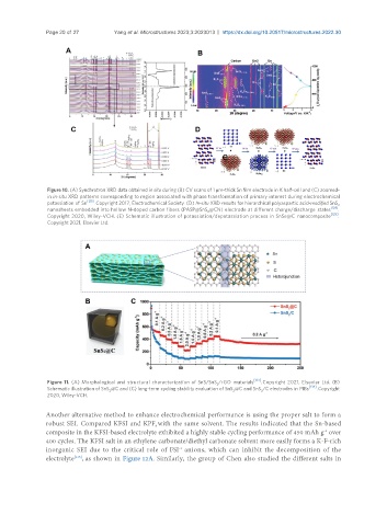
Figure 11. (A) Morphological and structural characterization of SnS/SnS /rGO materials . Copyright 2021, Elsevier Ltd. (B)
2
[134]
Schematic illustration of SnS @C and (C) long-term cycling stability evaluation of SnS @C and SnS /C electrodes in PIBs . Copyright
2 2 2
2020, Wiley-VCH.
Another alternative method to enhance electrochemical performance is using the proper salt to form a
robust SEI. Compared KFSI and KPF with the same solvent. The results indicated that the Sn-based
6
composite in the KFSI-based electrolyte exhibited a highly stable cycling performance of 450 mAh g over
-1
400 cycles. The KFSI salt in an ethylene carbonate/diethyl carbonate solvent more easily forms a K-F-rich
-1
inorganic SEI due to the critical role of FSI anions, which can inhibit the decomposition of the
[135]
electrolyte , as shown in Figure 12A. Similarly, the group of Chen also studied the different salts in