
Page 76 - Read Online
P. 76
Page 10 of 27 Yang et al. Microstructures 2023;3:2023013 https://dx.doi.org/10.20517/microstructures.2022.30
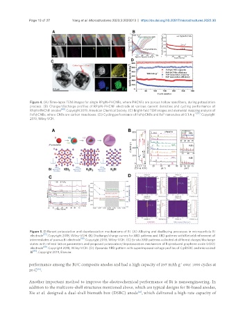
Figure 4. (A) Time-lapse TEM images for single RP@N-PHCNFs, where PHCNFs are porous hollow nanofibers, during potassiation
process. (B) Charge/discharge profiles of RP@N-PHCNF electrode at various current densities and cycling performance of
[40]
RP@N-PHCNF anodes . Copyright 2019, American Chemical Society. (C) Bright-field TEM images and elemental mapping analysis of
FeP@CNBs, where CNBs are carbon nanoboxes. (D) Cycling performance of FeP@CNBs and FeP nanocubes at 0.1 A g -1 [52] . Copyright
2019, Wiley VCH.
Figure 5. Different potassiation and depotassiation mechanisms of Bi. (A) Alloying and dealloying processes in microparticle Bi
electrode [57] . Copyright 2018, Wiley-VCH. (B) Discharge/charge curves for XRD patterns and XRD patterns with Rietveld refinement of
intermediates of porous Bi electrode [58] . Copyright 2018, Wiley-VCH. (C) Ex-situ XRD patterns collected at different charge/discharge
states with refined lattice parameters and proposed potassiation/depotassiation mechanism of Bi@reduced graphene oxide (rGO)
[59]
electrode . Copyright 2018, Wiley-VCH. (D) Operando XRD pattern with superimposed voltage profiles of C@DSBC and microsized
[60]
Bi . Copyright 2019, Elsevier.
performance among the Bi/C composite anodes and had a high capacity of 297 mAh g over 1000 cycles at
-1
[66]
20 C .
Another important method to improve the electrochemical performance of Bi is nanoengineering. In
addition to the multicore-shell structures mentioned above, which are typical designs for Bi-based anodes,
Xie et al. designed a dual-shell bismuth box (DSBC) anode , which delivered a high-rate capacity of
[60]