
Page 46 - Read Online
P. 46
Page 6 of 25 Dela Cruz et al. Microstructures 2023;3:2023012 https://dx.doi.org/10.20517/microstructures.2022.33
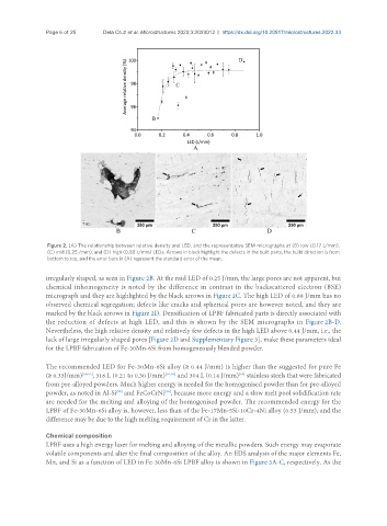
Figure 2. (A) The relationship between relative density and LED, and the representative SEM micrographs at (B) low (0.17 J/mm),
(C) mid (0.25 /mm), and (D) high (0.88 J/mm) LEDs. Arrows in black highlight the defects in the built parts, the build direction is from
bottom to top, and the error bars in (A) represent the standard error of the mean.
irregularly shaped, as seen in Figure 2B. At the mid LED of 0.25 J/mm, the large pores are not apparent, but
chemical inhomogeneity is noted by the difference in contrast in the backscattered electron (BSE)
micrograph and they are highlighted by the black arrows in Figure 2C. The high LED of 0.88 J/mm has no
observed chemical segregation; defects like cracks and spherical pores are however noted, and they are
marked by the black arrows in Figure 2D. Densification of LPBF fabricated parts is directly associated with
the reduction of defects at high LED, and this is shown by the SEM micrographs in Figure 2B-D.
Nevertheless, the high relative density and relatively few defects in the high LED above 0.44 J/mm, i.e., the
lack of large irregularly shaped pores [Figure 2D and Supplementary Figure 3], make these parameters ideal
for the LPBF fabrication of Fe-30Mn-6Si from homogeneously blended powder.
The recommended LED for Fe-30Mn-6Si alloy (≥ 0.44 J/mm) is higher than the suggested for pure Fe
(≥ 0.33J/mm) [50,51] , 316 L (0.21 to 0.30 J/mm) [52,53] and 304 L (0.14 J/mm) stainless steels that were fabricated
[54]
from pre-alloyed powders. Much higher energy is needed for the homogenised powder than for pre-alloyed
[56]
[55]
powder, as noted in Al-Si and FeCoCrNi , because more energy and a slow melt pool solidification rate
are needed for the melting and alloying of the homogenised powder. The recommended energy for the
LPBF of Fe-30Mn-6Si alloy is, however, less than of the Fe-17Mn-5Si-10Cr-4Ni alloy (0.53 J/mm), and the
difference may be due to the high melting requirement of Cr in the latter.
Chemical composition
LPBF uses a high energy laser for melting and alloying of the metallic powders. Such energy may evaporate
volatile components and alter the final composition of the alloy. An EDS analysis of the major elements Fe,
Mn, and Si as a function of LED in Fe-30Mn-6Si LPBF alloy is shown in Figure 3A-C, respectively. As the