
Page 90 - Read Online
P. 90
Page 4 of 13 Liu et al. Microstructures 2023;3:2023008 https://dx.doi.org/10.20517/microstructures.2022.31
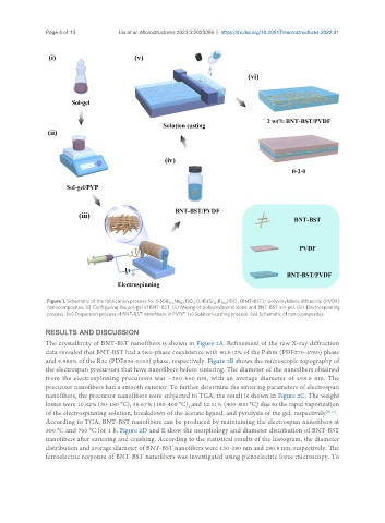
Figure 1. Schematic of the fabrication process for 0.55Bi Na TiO -0.45(Sr Bi )TiO (BNT-BST)/ polyvinylidene difluoride (PVDF)
0.5 0.5 3 0.7 0.2 3
nanocomposites. (i) Configuring the sol-gel of BNT-BST. (ii) Mixing of polyvinylpyrrolidone and BNT-BST sol-gel. (iii) Electrospinning
process. (iv) Dispersion process of BNT-BST nanofibers in PVDF. (v) Solution-casting process. (vi) Schematic of nanocomposites.
RESULTS AND DISCUSSION
The crystallinity of BNT-BST nanofibers is shown in Figure 2A. Refinement of the raw X-ray diffraction
data revealed that BNT-BST had a two-phase coexistence with 90.012% of the P4bm (PDF#70-4760) phase
and 9.988% of the R3c (PDF#36-0153) phase, respectively. Figure 2B shows the microscopic topography of
the electrospun precursors that have nanofibers before sintering. The diameter of the nanofibers obtained
from the electrospinning precursors was ~260-650 nm, with an average diameter of 498.8 nm. The
precursor nanofibers had a smooth exterior. To further determine the sintering parameters of electrospun
nanofibers, the precursor nanofibers were subjected to TGA; the result is shown in Figure 2C. The weight
losses were 10.82% (30-180 °C), 38.67% (180-400 °C), and 12.11% (400-800 °C) due to the rapid vaporization
of the electrospinning solution, breakdown of the acetate ligand, and pyrolysis of the gel, respectively [30,31] .
According to TGA, BNT-BST nanofibers can be produced by maintaining the electrospun nanofibers at
300 °C and 700 °C for 1 h. Figure 2D and E show the morphology and diameter distribution of BNT-BST
nanofibers after sintering and crushing. According to the statistical results of the histogram, the diameter
distribution and average diameter of BNT-BST nanofibers were 150-380 nm and 280.8 nm, respectively. The
ferroelectric response of BNT-BST nanofibers was investigated using piezoelectric force microscopy. To