


Page 52 - Read Online
P. 52
Page 10 of 17                                                       Zhang et al. Soft Sci. 2026, 6, 16


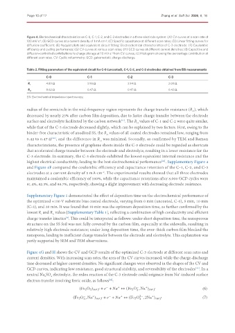
               Figure 4. Electrochemical characteristics on C-0, C-1, C-2, and C-3 electrodes in a three-electrode system: (A) CV curves at a scan rate of
               100 mV·s ; (B) GCD curves at a current density of 1 mA·cm ; (C) Specific capacitance at different scan rates; (D) Linear fitting curves for
                                                      -2
                     -1
               diffusion coefficient; (E) Nyquist plots and equivalent circuit fitting; Electrochemical characteristics of C-3 electrode: (F) Coulombic
               efficiency and cycling performance; (G) CV curves at various scan rates; (H) GCD curves at different current densities; (I) Capacitive and
               diffusion-controlled contributions to charge storage at 10 mV·s  from CV curves; (J) Histogram showing the percentage contribution at
                                                         -1
               different scan rates. CV: Cyclic voltammetry; GCD: galvanostatic charge-discharge.
               Table 2. Fitting parameters of the equivalent circuit for C-0 (uncoated), C-1, C-2, and C-3 electrodes obtained from EIS measurements

                        C-0                  C-1                  C-2                 C-3
                        4.89 Ω               3.98 Ω               3.94 Ω              2.08 Ω
               R s
                        0.62 Ω               0.47 Ω               0.47 Ω              0.42 Ω
               R ct
               EIS: Electrochemical impedance spectroscopy.


               radius of the semicircle in the mid-frequency region represents the charge transfer resistance (R ), which
                                                                                                  ct
               decreased by nearly 25% after carbon film deposition, due to faster charge transfer between the electrode
               surface and electrolyte facilitated by the carbon network . The R  values of C-1 and C-2 were quite similar,
                                                              [41]
                                                                      ct
               while that of the C-3 electrode decreased slightly, which can be explained by two factors. First, owing to the
               binder-free characteristic of anodized SS, the R  values of all coated electrodes remained low, ranging from
                                                       ct
               0.42 to 0.47 Ω , and the difference in R  was minimal. Secondly, as confirmed by TEM and Raman
                           [42]
                                                    ct
               characterizations, the presence of graphene sheets inside the C-3 electrode could be regarded as shortcuts
               that accelerated charge transfer between the electrode and electrolyte, resulting in a lower resistance for the
               C-3 electrode. In summary, the C-3 electrode exhibited the lowest equivalent internal resistance and the
               highest electrical conductivity, leading to the best electrochemical performance . Supplementary Figure 4
                                                                                   [43]
               and Figure 4F compared the coulombic efficiency and capacitance retention of the C-1, C-2, and C-3
               electrodes at a current density of 3 mA·cm . The experimental results showed that all three electrodes
                                                     -2
               maintained a coulombic efficiency of 100%, while the capacitance retentions after 8,000 GCD cycles were
               81.4%, 82.3%, and 88.7%, respectively, showing a slight improvement with decreasing electrode resistance.


               Supplementary Figure 5 demonstrated the effect of deposition time on the electrochemical performance of
               the optimized +100 V substrate bias coated electrode, varying from 0 min (uncoated, C-0), 5 min, 10 min
               (C-3), and 20 min. It was found that 10 min was the optimum deposition time, as further confirmed by the
               lowest R  and R  values [Supplementary Table 1], reflecting a combination of high conductivity and efficient
                            ct
                      s
               charge transfer kinetics . This could be interpreted as follows: under short deposition time, the nanoporous
                                  [4]
               structure on the SS foil was not fully covered by the carbon film, especially at the sidewalls, resulting in
               relatively high electrode resistance; under long deposition time, the over-thick carbon film blocked the
               nanopores, leading to inefficient charge transfer between the electrode and electrolyte. This explanation was
               partly supported by SEM and TEM observations.


               Figure 4G and H shows the CV and GCD results of the optimized C-3 electrode at different scan rates and
               current densities. With increasing scan rates, the area of the CV curves increased, while the charge-discharge
               time decreased at higher current densities. No significant changes were observed in the shapes of the CV and
               GCD curves, indicating low resistance, good structural stability, and reversibility of the electrodes . In a
                                                                                                    [44]
               neutral Na SO  electrolyte, the redox reaction of the C-3 electrode could originate from Na -induced surface
                                                                                            +
                        2
                           4
               electron transfer involving ferric oxide, as follows :
                                                        [45]
                                                       −     +        −    +
                                         (Fe 2 O 3 )           +    +      ↔ (Fe 2 O , Na )             (6)
                                                                      3
                                           −    +       −     +         2−    +
                                      (Fe 2 O , Na )           +    +      ↔ (Fe 2 O , 2Na )            (7)
                                           3                            3

