


Page 54 - Read Online
P. 54
Page 12 of 17                                                       Zhang et al. Soft Sci. 2026, 6, 16


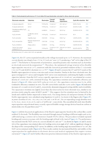
               Table 3. Electrochemical performance of C-3 and other SS-based electrodes evaluated in a three-electrode system
                                                           Current    Specific
               Electrode materials  Substrate    Electrolyte                         Cycle life retention Ref.
                                                           density    capacitance
               N-doped oxidized SS  SS foil      1 M Na 2 SO 4  1.0 mA·cm -2  321.3 mF·cm -2  500%-70.0%  [5]
               N-doped oxidized SS  SS foil      1 M Na 2 SO 4  1.0 mA·cm -2  332.3 mF·cm -2  8,000%-76.6%  [11]
               Phosphate modified Fe 2 O 3  CC   6 M KOH   5.0 mV·s -1  520.0 F·g -1  10,000%-80.1%  [52]
               nanoparticles
                                 Conductive carbon
               Fe 2 O 3  nanowire                1 M Na 2 SO 4  1.0 mA·cm -2  215.0 mF·cm -2  N/A   [53]
                                 fabric
               Fe 2 O 3  nanocube  Graphite sheet  3 M KOH  2.0 A/g   908.0 F·g -1   1,000%-65.0%   [54]
                                 Nitrogen-doped wood
               Fe 2 O 3  nanoparticle            3 M KOH   0.1 A/g    603.0 F·g -1   10,000%-85.5%  [55]
                                 carbons
               Fe 2 O 3  octahedron  Glassy carbon  6 M KOH  0.5 A/g  274.0 F·g -1   5,000%-83.0%   [56]
               Carbon film coated  SS foil                 1.0 mA·cm  (1.9 271.6 mF·cm  (512.5  8,000%-88.7%  This
                                                                 -2
                                                                              -2
               oxidized SS (C-3)                 1 M Na 2 SO 4  A/g)  F/g)                          work
               SS: Stainless steel; CC: carbon cloth; N/A: not applicable.
               Figure 5A, the CV curves expanded steadily as the voltage increased up to 1.8 V. However, the maximum
               current density rose sharply from 17.5 to 27.5 mA·cm  near 2.0 V, producing a “tail” at the edge of the CV
                                                             -2
               curve . This behavior is characteristic of polarization, caused by parasitic side reactions such as electrolyte
                   [57]
               or electrode material decomposition [58] . Therefore, the optimized voltage window of the flexible
               supercapacitor was set at 1.8 V, consistent with the theoretical potential windows of the C-3 electrode
               (-0.8~0.0 V) and AC@CC electrode (0.0-1.0 V) . Figure 5B and C presents the CV and GCD results of the
                                                       [12]
               flexible supercapacitor at various scan rates and current densities. Similar to the three-electrode tests, the
               quasi-rectangular CV curves and triangular GCD curves were maintained, confirming the highly reversible
               capacitive behavior. From the GCD curves, a specific capacitance of 101.50 mF·cm  was obtained at a current
                                                                                    -2
               density of 1.0 mA·cm , with a minimal IR-drop. The capacitance retention and Coulombic efficiency are
                                 -2
               shown in Figure 5D. After 8,000 GCD cycles at 3 mA·cm , the capacitance retention was 79.2%, while
                                                                  -2
               Coulombic efficiency remained at 100%. The EIS curves before and after 8,000 cycles [Figure 5E] indicated
               increases of 1.12 and 0.08 Ω in R  and R , respectively, demonstrating good cycling stability and reversibility.
                                          s
                                                ct
               The capacitance retention was slightly lower than that observed in the three-electrode tests, similar to our
               previous study using the same AC@CC anode . This suggests that the retention may be limited by the
                                                       [12]
               anode and could be further improved in future work. The energy density (E) and power density (P) of the
               flexible supercapacitor were calculated using Equations (2) and (3). As shown in the Ragone plot [Figure 5F],
               at power densities of 0.50, 1.00, 2.00, 3.24, 5.80, and 13.40 W·cm , the corresponding energy densities were
                                                                      -3
               51.70, 50.21, 44.63, 39.49, 29.72, and 11.87 mWh·cm , respectively. The assembled all-solid-state flexible
                                                            -3
               supercapacitor outperformed many recently reported flexible energy storage devices based on carbon or
               metal oxides over the past three years [59-66] .


               Figure 6 exhibits the practical applications of the flexible supercapacitor based on the carbon film-coated
               oxidized SS electrode. The flexibility was evaluated through manual bending at different angles and cycles,
               calibrated using a commercial inclinometer (Syatek SYLF5, China). The procedure included repeated
               bending and recovery processes, with the bending angle defined in the inset of Figure 6A. The performance
               was assessed from the GCD curves at a current density of 1 mA·cm -2[67] . As shown in Figure 6A and B, nearly
               90% of the capacitance was retained after 600 bending cycles at an angle of 60°, with no significant change in
               the shape of the corresponding GCD curves. In addition, as the bending angle increased from 60° to 180°, the
               GCD curves remained stable [Figure 6C]. These results confirm the mechanical flexibility and stability of the
               supercapacitor for applications in electronic devices and medical equipment that require various
               curvatures . Figure 6D and E further illustrates practical demonstrations of the flexible supercapacitor,
                        [68]

