


Page 134 - Read Online
P. 134
Page 12 of 19                                                        Chen et al. Soft Sci. 2026, 6, 48


               its initial dimension. In the present static experimental setup, the final stage of recovery occurs on the order
               of min, reflecting passive cooling of the sealed phase-change medium. It is also worth noting the balloon’s
               mass remains nearly constant throughout the expansion and deflation cycle, indicating a well-sealed
               assembly with minimal leakage.


               When the balloon is microwave-heated in small vessels, it first expands freely until it contacts the vessel wall,
               at which point the internal pressure equals p  from Figure 3B. Further inflation will exert output pressure
                                                     free
               (denoted as p ) on the vessel. The output pressure can be calculated as
                          out
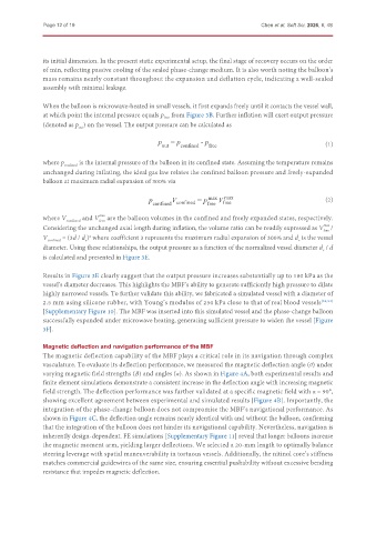
                                                   p  = p        - p                                    (1)
                                                    out   confined  free

               where p confined  is the internal pressure of the balloon in its confined state. Assuming the temperature remains
               unchanged during inflating, the ideal gas law relates the confined balloon pressure and freely-expanded
               balloon at maximum radial expansion of 300% via


                                                       V
                                                p confined confined  = p  max V  max                    (2)
                                                                        free
                                                                   free
               where V confined  and V  are the balloon volumes in the confined and freely expanded states, respectively.
                                 max

                                free
               Considering the unchanged axial length during inflation, the volume ratio can be readily expressed as V  /
                                                                                                        max

                                                                                                       free
               V confined  = (3d / d )  where coefficient 3 represents the maximum radial expansion of 300% and d  is the vessel
                             2
                                                                                               v
                            v
               diameter. Using these relationships, the output pressure as a function of the normalized vessel diameter d  / d
                                                                                                       v
               is calculated and presented in Figure 3E.
               Results in Figure 3E clearly suggest that the output pressure increases substantially up to 180 kPa as the
               vessel’s diameter decreases. This highlights the MBF’s ability to generate sufficiently high pressure to dilate
               highly narrowed vessels. To further validate this ability, we fabricated a simulated vessel with a diameter of
               2.5 mm using silicone rubber, with Young’s modulus of 250 kPa close to that of real blood vessels [53,54]
               [Supplementary Figure 10]. The MBF was inserted into this simulated vessel and the phase-change balloon
               successfully expanded under microwave heating, generating sufficient pressure to widen the vessel [Figure
               3F].


               Magnetic deflection and navigation performance of the MBF
               The magnetic deflection capability of the MBF plays a critical role in its navigation through complex
               vasculature. To evaluate its deflection performance, we measured the magnetic deflection angle (θ) under
               varying magnetic field strengths (B) and angles (α). As shown in Figure 4A, both experimental results and
               finite element simulations demonstrate a consistent increase in the deflection angle with increasing magnetic
               field strength. The deflection performance was further validated at a specific magnetic field with α = 90°,
               showing excellent agreement between experimental and simulated results [Figure 4B]. Importantly, the
               integration of the phase-change balloon does not compromise the MBF’s navigational performance. As
               shown in Figure 4C, the deflection angle remains nearly identical with and without the balloon, confirming
               that the integration of the balloon does not hinder its navigational capability. Nevertheless, navigation is
               inherently design-dependent. FE simulations [Supplementary Figure 11] reveal that longer balloons increase
               the magnetic moment arm, yielding larger deflections. We selected a 20-mm length to optimally balance
               steering leverage with spatial maneuverability in tortuous vessels. Additionally, the nitinol core’s stiffness
               matches commercial guidewires of the same size, ensuring essential pushability without excessive bending
               resistance that impedes magnetic deflection.

