


Page 140 - Read Online
P. 140
Page 30 of 57                                                       Zheng et al. Soft Sci. 2026, 6, 32


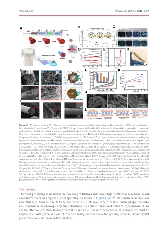
               Figure 11. (A) Fabrication of MGP-T fiber via continuous wet spinning and thermal drawing, and the formation of MXene-based textiles.
               Reproduced with permission [119] , Copyright © 2022 Springer Nature; (B) Relationship between the MXene ink concentration (volumetric
               and mass) and the flake size (lateral size and aspect ratio) for isotropic to nematic phase transformation based on theoretical calculations.
               The stars represent the theoretical LC transition concentrations for L-Ti 3 C 2  and S-Ti 3 C 2  dispersions based on their average flake size
               (3.1 μm and 310 nm, respectively); (C) POM images of aqueous L-Ti 3 C 2  and S-Ti 3 C 2  inks at various concentrations demonstrating the
               nematic LC formation based on flake size and concentration; (D) Viscoelastic behavior of L-Ti 3 C 2  at a concentration of 26.5 mg·mL  (red
                                                                                                       -1
               solid symbols) and S-Ti 3 C 2  at a concentration of 150 mg·mL  (black hollow symbols); (E) Frequency dependency on G’/G” ratio for the
                                                       -1
               L-Ti 3 C 2  and S-Ti 3 C 2  MXene inks; (F) Cross-sectional SEM images of LC MXene fibers using S-Ti 3 C 2  flakes produced in an acetic acid bath.
               Schematic illustration of the fast coagulation mechanism when acetic acid was used as the coagulation bath (above). Cross-sectional SEM
               images of S-Ti 3 C 2  fibers produced in the chitosan bath. Schematic illustration of the slow coagulation mechanism when chitosan was used
               as the coagulation bath (below). (B-F) are reprinted with permission from Ref.  [33] , Copyright © 2020 American Chemical Society; (G)
               digital photograph of a ≈ 100-m-long MXene/PU fiber. Reproduced with permission [142] , Copyright © 2020 John Wiley and Sons; (H)
               Nitrogen adsorption-desorption isotherm of MAF with different dispersion concentrations. The inset is the corresponding specific surface
               area; (I) Cross-section and surface morphologies of the Ti 3 C 2 T x  MXene aerogel fibers. (H and I) are reprinted with permission from Ref. [28] ,
               Copyright © 2021 John Wiley and Sons; (J) Cross section SEM images of overall fracture surface and MXene core; (K) Typical tensile
               stress-strain curves; (L) Proposed fracture process of ANF@M fibers. (J-I) are reprinted with permission from Ref. [114] , Copyright © 2022
               Springer Nature. MGP-T: MXene-glutaraldehyde-polyvinyl alcohol fiber after thermal drawing; LC: liquid crystalline; POM: polarizing
               optical microscope; SEM: scanning electron microscope; PU: polyurethane; MAF: MXene aerogel fiber; ANF: aramid nanofiber; PVA:
               polyvinyl alcohol; MG: MXene-glutaraldehyde fiber; ET: electrothermal; EMI: electromagnetic interference.


               Wet spinning
               The most promising mainstream method for producing continuous, high-performance MXene-based
               conductive fibers on a big scale is wet-spinning. As shown in Figure 11A [37,143] , its fundamental idea is to
               assemble two-dimensional MXene nanosheets, which have exceptional intrinsic properties into
               one-dimensional macroscopic organized structures via a phase transition directed by hydrodynamics. To
               ensure effective structure transfer from the nanoscale to macroscopic fibers, this procedure must be
               implemented with systematic control over the rheological behavior of the spinning precursor, liquid crystal
               phase transitions, and solidification kinetics.

