
Page 9 - Read Online
P. 9
Peng et al. Soft Sci 2023;3:36 https://dx.doi.org/10.20517/ss.2023.28 Page 7 of 12
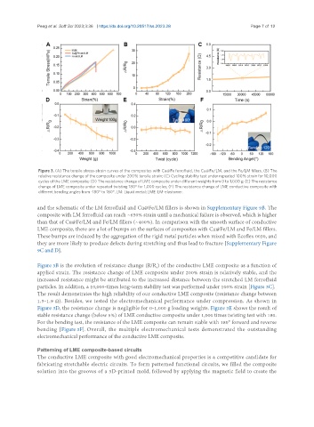
Figure 3. (A) The tensile stress-strain curves of the composites with Cu@Fe ferrofluid, the Cu@Fe/LM, and the Fe/LM fillers; (B) The
relative resistance change of the composite under 200% tensile strain; (C) Cycling stability test under repeated 100% strain for 10,000
cycles of the LME composite; (D) The resistance change of LME composite under different weights from 0 to 1,000 g; (E) The resistance
change of LME composite under repeated twisting 180° for 1,000 cycles; (F) The resistance change of LME conductive composite with
different bending angles from -180° to 180°. LM: Liquid metal; LME: LM-elastomer.
and the schematic of the LM ferrofluid and Cu@Fe/LM fillers is shown in Supplementary Figure 9B. The
composite with LM ferrofluid can reach ~650% strain until a mechanical failure is observed, which is higher
than that of Cu@Fe/LM and Fe/LM fillers (~400%). In comparison with the smooth surface of conductive
LME composite, there are a lot of bumps on the surfaces of composites with Cu@Fe/LM and Fe/LM fillers.
These bumps are induced by the aggregation of the rigid metal particles when mixed with Ecoflex 0030, and
they are more likely to produce defects during stretching and thus lead to fracture [Supplementary Figure
9C and D].
Figure 3B is the evolution of resistance change (R/R ) of the conductive LME composite as a function of
0
applied strain. The resistance change of LME composite under 200% strain is relatively stable, and the
increased resistance might be attributed to the increased distance between the stretched LM ferrofluid
particles. In addition, a 10,000-times long-term stability test was performed under 100% strain [Figure 3C].
The result demonstrates the high reliability of our conductive LME composite (resistance change between
1.5-1.9 Ω). Besides, we tested the electromechanical performance under compression. As shown in
Figure 3D, the resistance change is negligible for 0-1,000 g loading weights. Figure 3E shows the result of
stable resistance change (below 5%) of LME conductive composite under 1,000 times twisting test with 180.
For the bending test, the resistance of the LME composite can remain stable with 180° forward and reverse
bending [Figure 3F]. Overall, the multiple electromechanical tests demonstrated the outstanding
electromechanical performance of the conductive LME composite.
Patterning of LME composite-based circuits
The conductive LME composite with good electromechanical properties is a competitive candidate for
fabricating stretchable electric circuits. To form patterned functional circuits, we filled the composite
solution into the grooves of a 3D-printed mold, followed by applying the magnetic field to create the