
Page 10 - Read Online
P. 10
Page 8 of 12 Peng et al. Soft Sci 2023;3:36 https://dx.doi.org/10.20517/ss.2023.28
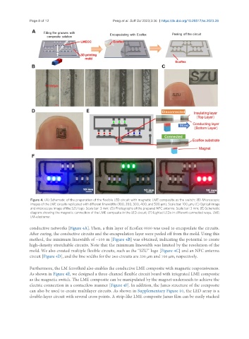
Figure 4. (A) Schematic of the preparation of the flexible LED circuit with magnetic LME composite as the switch; (B) Microscopic
images of the LME circuits replicated with different linewidths (100, 200, 300, 400, and 500 μm). Scale bar: 100 μm; (C) Optical image
and microscope image of the SZU logo. Scale bar: 3 mm; (D) Photographs of the prepared NFC antenna. Scale bar: 3 mm; (E) Schematic
diagram showing the magnetic connection of the LME composite in the LED circuit; (F) Lighted LEDs in different connected ways. LME:
LM-elastomer.
conductive networks [Figure 4A]. Then, a thin layer of Ecoflex 0030 was used to encapsulate the circuits.
After curing, the conductive circuits and the encapsulation layer were peeled off from the mold. Using this
method, the minimum linewidth of ~100 m [Figure 4B] was obtained, indicating the potential to create
high-density stretchable circuits. Note that the minimum linewidth was limited by the resolution of the
mold. We also created multiple flexible circuits, such as the “SZU” logo [Figure 4C] and an NFC antenna
circuit [Figure 4D], and the line widths for the two circuits are 200 µm and 100 µm, respectively.
Furthermore, the LM ferrofluid also enables the conductive LME composite with magnetic responsiveness.
As shown in Figure 4E, we designed a three-channel flexible circuit board with integrated LME composite
as the magnetic switch. The LME composite can be manipulated by the magnet underneath to achieve the
electric connection in a contactless manner [Figure 4F]. In addition, the Janus structure of the composite
can also be used to create multilayer circuits. As shown in Supplementary Figure 10, the LED array is a
double-layer circuit with several cross points. A strip-like LME composite Janus film can be easily stacked