
Page 8 - Read Online
P. 8
Page 6 of 12 Peng et al. Soft Sci 2023;3:36 https://dx.doi.org/10.20517/ss.2023.28
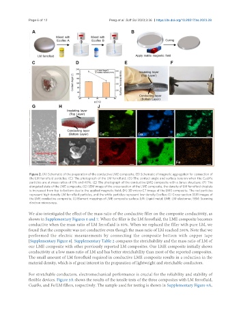
Figure 2. (A) Schematic of the preparation of the conductive LME composite; (B) Schematic of magnetic aggregation for connection of
the LM ferrofluid particles; (C) The photograph of the LM ferrofluid; (D) The contact angle and surface tension when the Cu@Fe
particles are at mass ratios of 0% and 40%; (E) The photograph of the conductive LME composite with a Janus structure; (F) The
elongated state of the LME composite; (G) SEM image of the cross-section of the LME composite, the density of LM ferrofluid droplets
is increased from top to bottom due to the applied magnetic field; (H) 3D micro-CT image of the LME composite. The red particles
represent high-density LM ferrofluid particles, and the white particles represent low-density Ecoflex; (I) Cross-section SEM images of
the LME conductive composite; (J) Element mappings of LME composite surface. LM: Liquid metal; LME: LM-elastomer; SEM: Scanning
electron microscopy.
We also investigated the effect of the mass ratio of the conductive filler on the composite conductivity, as
shown in Supplementary Figures 6 and 7. When the filler is the LM ferrofluid, the LME composite becomes
conductive when the mass ratio of LM ferrofluid is 80%. When we replaced the filler with pure LM, we
found that the composite was not conductive even though the mass ratio of LM reached 200%. Note that we
performed the electric measurements by connecting the composite bottom with copper tape
[Supplementary Figure 8]. Supplementary Table 2 compares the stretchability and the mass ratio of LM of
our LME composite with other previously reported LM composites. Our LME composite initially shows
conductivity at a low mass ratio of LM and has better stretchability than most of the reported composites.
The small amount of LM ferrofluid required in conductive LME composite results in a reduction in the
material density, which is of great interest in the preparation of lightweight and stretchable conductors.
For stretchable conductors, electromechanical performance is crucial for the reliability and stability of
flexible devices. Figure 3A shows the results of the tensile tests of the three composites with LM ferrofluid,
Cu@Fe, and Fe/LM fillers, respectively. The sample used for testing is shown in Supplementary Figure 9A,