
Page 7 - Read Online
P. 7
Page 4 of 26 Xiao et al. Soft Sci 2023;3:11 https://dx.doi.org/10.20517/ss.2023.03
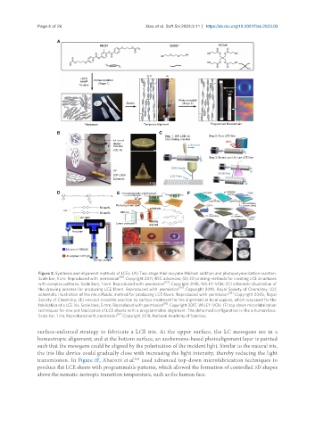
Figure 2. Synthesis and alignment methods of LCEs. (A) Two-stage thiol-acrylate Michael addition and photopolymerization reaction.
[56]
Scale bar, 1 cm. Reproduced with permission . Copyright 2011, RSC advances; (B) 3D printing methods for creating LCE structures
[57]
with complex patterns. Scale bars, 1 mm. Reproduced with permission . Copyright 2018, WILEY-VCH; (C) schematic illustration of
the drawing process for producing LCE fibers. Reproduced with permission [54] . Copyright 2019, Royal Society of Chemistry; (D)
schematic illustration of the microfluidic method for producing LCE fibers. Reproduced with permission [59] . Copyright 2005, Royal
Society of Chemistry; (E) one-pot crosslink reaction by surface treatment for the alignment at local regions, which was used for the
fabrication of a LCE iris. Scale bars, 5 mm. Reproduced with permission [61] . Copyright 2017, WILEY-VCH; (F) top-down microfabrication
techniques for one-pot fabrication of LCE sheets with a programmable alignment. The deformed configuration is like a human face.
Scale bar, 1 cm. Reproduced with permission [62] . Copyright 2018, National Academy of Sciences.
surface-enforced strategy to fabricate a LCE iris. At the upper surface, the LC mesogens are in a
homeotropic alignment; and at the bottom surface, an azobenzene-based photoalignment layer is painted
such that the mesogens could be aligned by the polarization of the incident light. Similar to the natural iris,
the iris-like device could gradually close with increasing the light intensity, thereby reducing the light
transmission. In Figure 2F, Aharoni et al. used advanced top-down microfabrication techniques to
[62]
produce flat LCE sheets with programmable patterns, which allowed the formation of controlled 3D shapes
above the nematic-isotropic transition temperature, such as the human face.