
Page 136 - Read Online
P. 136
Ruiz-Moya et al. Assessment of DIEP flap using CTA with 3D reconstruction
reconstruction, that did not exhibit previous nor a Digital Imaging and Communications in Medicine
other vascular complication, such as arteriovenous (DICOM) compatible file on a CD-ROM to be uploaded
®
thrombosis or necrosis. to a personal computer with the AYRA software
(formerly known as VirSSPA ; Andalusian Health
®
Thirty-seven reconstructions were excluded as the Department, Seville, Spain). The 3D reconstructions
preoperative perforator mapping was performed with a of the abdominal wall were generated using the
hand-held Doppler probe. Four flaps that had exhibited DICOM files by means of the virtual reality AYRA
®
vascular complications different to diffuse venous software. All the variables were assessed in these 3D
congestion (2 cases of intraoperative partial venous virtual models.
congestion related to abdominal midline scars, 1 case
of intraoperative venous thrombosis, and 1 case of late Evaluation of the images
venous thrombosis 6 days following the surgery) were The preoperative 3D reconstruction of each case
discarded as well. The final sample group included was retrieved by the same observer (A. Ruiz-
data from 169 DIEP flaps. According to the inclusion Moya). The following anatomical variables were
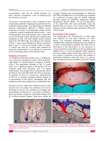
criteria, 7 cases were identified as diffuse congestive retrospectively analyzed in both groups: the existence
flaps [Figure 1]. Due to the limited number of cases, of direct communications between the SIEV and the
3 controls per case (21 controls) were selected by perforators of the flap [Figure 2], the existence of
computer randomization, in an attempt to control the communications of both SIEVs across the abdominal
power of the study and to avoid selection bias. midline [Figure 3], the 8-cm-diameter SIEV caudal to
the most superior aspect of the iliac crests [Figure 4],
Imaging procedures the number of branches of the SIEV, the number of
The studies of CTA were carried out by a 16-detector- perforators included in each flap [Figure 5], and the
row computed tomography scanner (General Electric flap subcutaneous tissue thickness at a point located
Light-Speed 16; General Electric Company, Fairfield,
Conn.). The parameters followed by the CT scans
were: 0.37 s rotational speed of the gantry, 0.63 mm
collimator width slice thickness, and 1.37 helical
detector pitch. The voltage of the X-ray tube was 120 kV
and tube current was 250 to 300 mA. Prior to scanning,
all patients received an intravenous administration
of 100 mL of nonionic iodinated contrast medium at
a concentration of 350 mg/mL (Omnipaque 350; GE
Healthcare, Barcelona, Spain) into an antecubital vein.
Sections of 0.63 in width were obtained at an 0.5-mm
interval from 4 cm above the umbilicus to the minor
trochanter of the hip. The resulting set of images was
automatically transferred to a computer workstation,
which generated multiplanar reformatted images and Figure 1: Deep inferior epigastric artery perforator flap exhibiting
3D volume-rendered images. Data were stored as diffuse venous congestion
Figure 2: Three-dimensional abdominal wall reconstruction with AYRA software from computed tomography angiography images. (A) Point
of assessment (circle) of direct communications between perforators (red) and superficial venous system (blue); (B) direct communications
viewed from the abdominal wall
Plastic and Aesthetic Research ¦ Volume 4 ¦ August 21, 2017 129