
Page 13 - Read Online
P. 13
Drobot et al. Plast Aesthet Res 2021;8:30 https://dx.doi.org/10.20517/2347-9264.2021.19 Page 7 of 11
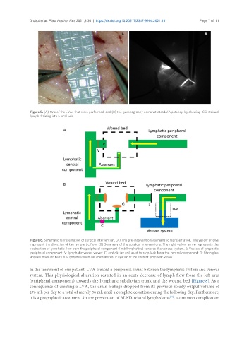
Figure 5. (A) One of the LVAs that were performed; and (B) the lymphography demonstrates LVA patency, by showing ICG-stained
lymph draining into a local vein.
Figure 6. Schematic representation of surgical intervention. (A) The pre-interventional schematic representation. The yellow arrows
represent the direction of the lymphatic flow. (B) Summary of the surgical interventions. The right yellow arrow represents the
redirection of lymphatic flow from the peripheral component (limb lymphatics) towards the venous system. E: Vessels of lymphatic
peripheral component; V: lymphatic vessel valves; C: embolizing coil used to stop leak from the central component; G: fibrin glue
applied in wound bed; LVA: lymphaticovenular anastomosis; L: ligation of the efferent lymphatic vessel.
In the treatment of our patient, LVA created a peripheral shunt between the lymphatic system and venous
system. This physiological alteration resulted in an acute decrease of lymph flow from the left arm
(peripheral component) towards the lymphatic subclavian trunk and the wound bed [Figure 6]. As a
consequence of creating a LVA, the drain leakage dropped from its previous steady output volume of
270 mL per day to a total of merely 50 mL until a complete cessation during the following day. Furthermore,
[25]
it is a prophylactic treatment for the prevention of ALND-related lymphedema , a common complication