
Page 705 - Read Online
P. 705
Page 8 of 10 Rodinò et al. Mini-invasive Surg 2020;4:70 I http://dx.doi.org/10.20517/2574-1225.2020.55
A B C
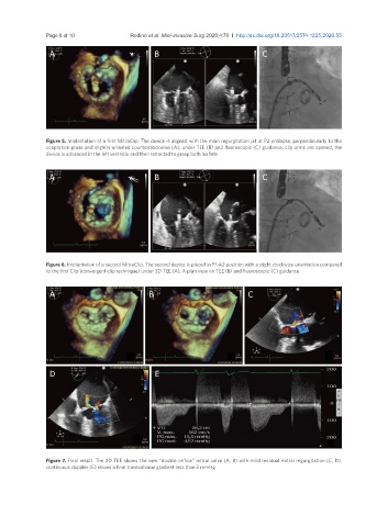
Figure 5. Implantation of a first MitraClip. The device is aligned with the main regurgitation jet at P2 prolapse, perpendicularly to the
coaptation plane and slightly oriented counterclockwise (A); under TEE (B) and fluoroscopic (C) guidance, clip arms are opened, the
device is advanced in the left ventricle and then retracted to grasp both leaflets
A B C
Figure 6. Implantation of a second MitraClip. The second device is placed in P1-A2 position with a slight clockwise orientation compared
to the first Clip (convergent clip technique) under 3D TEE (A), X-plan view on TEE (B) and fluoroscopic (C) guidance
A B C
D E
Figure 7. Final result. The 3D TEE shows the new “double orifice” mitral valve (A, B) with mild residual mitral regurgitation (C, D);
continuous doppler (E) shows a final transvalvular gradient less than 5 mmHg