
Page 79 - Read Online
P. 79
Zhang et al. Intell Robot 2022;2(4):37190 I http://dx.doi.org/10.20517/ir.2022.26 Page 385
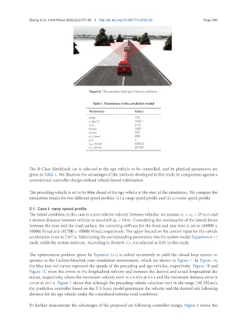
Figure 6. The scenario setting in Carsim platform.
Table 1. Parameters in the simulation model
Parameters Values
(kg) 1110
2 1343.1
(kg/m )
0 (s) 0.25
(mm) 1480
ℎ(mm) 350
(mm) 298
0 (s) 2
(N/rad) 66900
(N/rad) 62700
The B-Class Hatchback car is selected as the ego vehicle to be controlled, and its physical parameters are
given in Table 1. We illustrate the advantages of the methods developed in this study by comparison against a
conventional controller design without vehicle lateral stabilization.
The preceding vehicle is set to be 60m ahead of the ego vehicle at the start of the simulation. We compare the
simulation results for two different speed profiles: (1) a ramp speed profile and (2) a speed profile.
5.1. Case I: ramp speed profile
The initial condition in this case is a zero relative velocity between vehicles: we assume 1 = 2 = 25 m/s and
a desired distance between vehicles at standstill 0 = 10m. Considering the nonlinearity of the lateral forces
between the tires and the road surface, the cornering stiffness for the front and rear tires is set to (66900 ±
10000) N/rad and (62700 ± 10000) N/rad, respectively. The upper bound on the control input for the vehicle
acceleration is set to 2m /s. Substituting the corresponding parameters into the system model Equations 8-17
2
easily yields the system matrices. According to Remark 3.1, is selected as 0.01 in this study.
The optimization problem given by Equation (41) is solved recursively to yield the closed-loop system re-
sponses in the CarSim/Simulink joint simulation environment, which are shown in Figure 7. In Figure 7A,
the blue and red curves represent the speeds of the preceding and ego vehicles, respectively. Figure 7B and
Figure 7C show the errors in the longitudinal velocity and between the desired and actual longitudinal dis-
tances, respectively, where the maximum velocity error is 5.9 m/s at 4.5 s and the maximum distance error is
3.8 m at 19.7 s. Figure 7 shows that although the preceding vehicle velocities vary in the range [10, 25] m/s,
the predictive controller based on the T-S fuzzy model guarantees the velocity and the desired safe following
distance for the ego vehicle under the considered extreme road conditions.
To further demonstrate the advantages of the proposed car-following controller design, Figure 8 shows the