
Page 59 - Read Online
P. 59
Sun et al. Intell Robot 2022;2(4):35570 I http://dx.doi.org/10.20517/ir.2022.23 Page 365
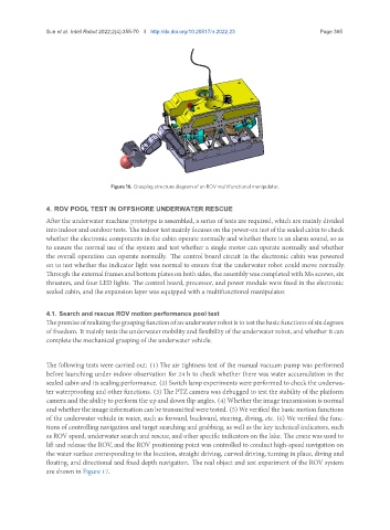
Figure 16. Grasping structure diagram of an ROV multifunctional manipulator.
4. ROV POOL TEST IN OFFSHORE UNDERWATER RESCUE
After the underwater machine prototype is assembled, a series of tests are required, which are mainly divided
into indoor and outdoor tests. The indoor test mainly focuses on the power-on test of the sealed cabin to check
whether the electronic components in the cabin operate normally and whether there is an alarm sound, so as
to ensure the normal use of the system and test whether a single motor can operate normally and whether
the overall operation can operate normally. The control board circuit in the electronic cabin was powered
on to test whether the indicator light was normal to ensure that the underwater robot could move normally.
Through the external frames and bottom plates on both sides, the assembly was completed with M6 screws, six
thrusters, and four LED lights. The control board, processor, and power module were fixed in the electronic
sealed cabin, and the expansion layer was equipped with a multifunctional manipulator.
4.1. Search and rescue ROV motion performance pool test
Thepremiseofrealizingthegraspingfunctionofanunderwaterrobotistotestthebasicfunctionsofsixdegrees
of freedom. It mainly tests the underwater mobility and flexibility of the underwater robot, and whether it can
complete the mechanical grasping of the underwater vehicle.
The following tests were carried out: (1) The air tightness test of the manual vacuum pump was performed
before launching under indoor observation for 24 h to check whether there was water accumulation in the
sealed cabin and its sealing performance. (2) Switch lamp experiments were performed to check the underwa-
ter waterproofing and other functions. (3) The PTZ camera was debugged to test the stability of the platform
camera and the ability to perform the up and down flip angles. (4) Whether the image transmission is normal
and whether the image information can be transmitted were tested. (5) We verified the basic motion functions
of the underwater vehicle in water, such as forward, backward, steering, diving, etc. (6) We verified the func-
tions of controlling navigation and target searching and grabbing, as well as the key technical indicators, such
as ROV speed, underwater search and rescue, and other specific indicators on the lake. The crane was used to
lift and release the ROV, and the ROV positioning point was controlled to conduct high-speed navigation on
the water surface corresponding to the location, straight driving, curved driving, turning in place, diving and
floating, and directional and fixed depth navigation. The real object and test experiment of the ROV system
are shown in Figure 17.