
Page 56 - Read Online
P. 56
Page 362 Sun et al. Intell Robot 2022;2(4):35570 I http://dx.doi.org/10.20517/ir.2022.23
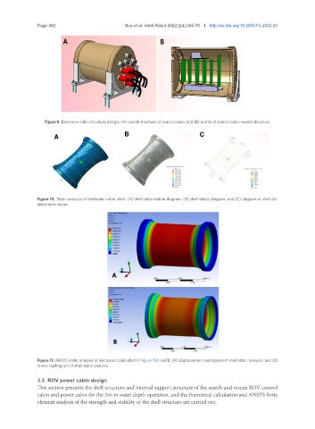
Figure 9. Electronic cabin structure design: (A) overall structure of control cabin; and (B) profile of control cabin overall structure.
A B C
Figure 10. Static analysis of electronic cabin shell: (A) shell deformation diagram; (B) shell stress diagram; and (C) diagram of shell dis-
placement vector.
Figure 11. ANSYS static analysis of electronic cabin shell in Figure 15A and B: (A) displacement nephogram of shell static analysis; and (B)
stress nephogram of shell static analysis.
3.3. ROV power cabin design
This section presents the shell structure and internal support structure of the search and rescue ROV control
cabin and power cabin for the 200 m water depth operation, and the theoretical calculation and ANSYS finite
element analysis of the strength and stability of the shell structure are carried out.